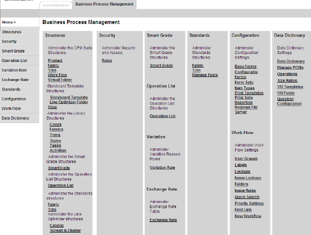
Use the Business Process Management section of the Administration module to setup the business rules and processes for the many modules of Fashion PLM.
The Business Process Management Tab
The Administrators are responsible for creating the structures for all of Fashion PLM. They must then assign team users and business partner locations and roles to the structures to gove them access.
The Smart Grade section allows Administrators to set up corporate grade rules for use on products.
Operation Lists define labor-related costs that factor into product costing.
Since many of the forms in Fashion PLM are configurable, you can design your own forms in the Configuration section. You can also create Item Types, Form Sets, Print Templates and Print Sets, and set up Report Launcher links for reports created in a third party tool.
The Workflow section is used to setup Workflow, while the Data Dictionary section allows for the configuration of drop down lists and items, points of measure, operations, and size ratios.
Figure37 Business Process Management tab
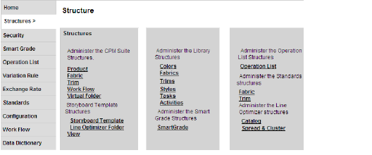
Use the Structure section of the Administration module to create the hierarchy for the various modules of Fashion PLM.
The Product structure will control the company’s folder hierarchy for storing products.
The Fabric structure will control the company’s folder hierarchy for storing fabrics.
The Trim structure will control the company’s folder hierarchy for storing trims.
The Storyboard Template structure will control the company’s folder hierarchy for storing storyboard templates.
The Line Optimizer Folder View structure will control the company’s folder hierarchy for storing Line Optimizer Folder View storyboard templates.
The Workflow structure will control the company’s folder hierarchy for storing activities and workflows.
The Library Structure controls the structure for color, fabric, trim, style, and task templates.
The Smart Grade structure allows you to store the various grade rules you will create for your products.
The Operation List structure allows you to store labour-related costs.
The Standards structure allows you to store your Fabric and Trim testing standards.
The Catalog and Spread/Cluster structures will control the company’s folder hierarchy for storing catalogues and spreads in Line Optimizer.
Security in Product Manager is controlled at the Role level. Roles control access levels (None, View, Edit) to different tabs (or sections), as well as different areas within a section (BOM, Colorway, Specifications, Costing, etc.) that a user may have.
The Smart Grade section of the Business Process Management is a critical part of product specifications. You can create, store and modify corporate grade rules for each possible combination of Product Type, Size Category, and Size Range.
You can create, store and modify corporate Operation Lists for each Product Type. The Operation List section allows you to enter labor time and cost information for sewing or pressing tasks that factor into the overall cost of your product.
The Variations section allows you to define how you want Line Optimizer to calculate product variations. Since products developed in Product Manager may be calculated in the Line Optimizer, product variations can be counted as part of the parent product or calculated as separate products.
Use the Exchange Rates section to manage seasonal currency exchange rates from the Master Company Currency. The Exchange rates are used on BOM items and Cost Scenarios in Source, allowing normalization of component costs to the cost scenario currency, and also calculation of product costs into multiple currencies, supporting global sourcing and distribution needs.
The Standards section is used with Fabric & Trim and comes loaded with industry standard tests. You may add new tests and create your own Performance standards by grouping selected tests together.
Configurable forms are variations of our Blank and Standard Forms that you may design for your company’s specific needs. They provide the flexibility to change field names, size, and positions. Add or hide fields, while maintaining the access levels defined for the forms in the company Roles. The Blank form is the one Base Form that allows you to define its Tab and Section names and is currently available for Product Manager products. Different variations of the same form may be created for various divisions.
Item Types are a combination of item information, Templates and Form Set. A Form Set is a predefined group of forms. Either or both can be selected while creating a new item in Fabric & Trim, Line Optimizer and Product Manager, and saves your users the extra steps of adding forms and templates individually to them.
Print Templates allow you to set up print information. When printing, you may want information to be printed differently than it appears on screen. You may also select to print different information depending on access rights, forms, applications, etc.
The Print Sets section allows you to group your Print Templates. You can select which forms to print as well as define access rights per division ensuring that your teams can execute standardized print jobs quickly and efficiently.
Using the Reporting module, you can setup general reports which can be used in all Fashion PLM applications, or configure module specific reports that are only available for selected Fashion PLM applications. Item reports can also be created and printed from an item.
Workflow administrative tasks are part of Fashion PLM and are linked to the administration of other modules such as Product Manager. User creation and business partner creation, as well as folder structure, are executed in the same screens used for all the other Fashion PLM modules.
Using Manage Fields, create User Fields, configure your drop-down lists, sort list items, rename items, create dependencies between fields, and add filtering between lists and items.
Manage POMs allows you to add and delete Point of Measures to the POM list.
Manage Operations allows you add operations to calculate labor-related costs for product costing.
Use Size Ratio to create size ratios that can be used in the Color Matrix window when creating Cost Requests in Product Manager.
Vendor Management Templates and Fields are used to set up vendors in Source.
Administrators can manage the structures for all Fashion PLM modules.
Figure38 Fashion PLM Strutures
Many of the Fashion PLM structures are based on seasons. The first level of the structure is then the All Seasons level. The Master Company Administrator may create as many Seasons-Years as needed to house the company styles.
Figure39 Product Structure Folder Levels
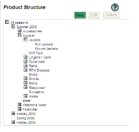
below the Season/Year level, there may be as many folder levels as needed, and their structure is flexible. While only the Master Company Administrator can add the first level of the structure, Division Administrators can manage the structure from the second level.
In most structures in Fashion PLM and in Administration, the bottom-level folder must be designated as a Node folder to enable the ability to create items in the structure since they are typically stared at the Node level. For example, products reside at the Product Node level, which must be designated as such. No other folder may be inserted below the Product Node level.
Fabric and Trim structures have designated Fabric and Trim Nodes. SmartGrade and Standard structures have SmartGrade and Standard Nodes. All Library structures have designated Nodes. Line Optimizer Spreads have a Spread/Cluster Node.
Line Optimizer Catalog structures have two levels of Nodes- a higher level called an Event Node where marketing information can be managed for all catalogs stored in folders below, and the bottom-level Catalog Node where catalogs are stored.
Workflows can be stored at any level of the Workflow structure in the Workflow Module and any level except Season/Year in the Product structure in Product Manager.
All Storyboards may be stored at any level of the Product structure except Season/Year in Storyboard. Product boards must be stored at the Node level because they can become actual products in Line Optimizer and Product Manager. Storyboard templates must be stored at the Node level in the Storyboard Template and Line Optimizer View Template structures.
Administrators and users who do not have access to a folder will not be able to view the folder or its contents. The Super Admin automatically sees all folders and their contents.
Folder details include the General Information, Security, and Properties. The General Information page allows you to define the folder name, season, year, descriptions, Deliveries, as well as assign Divisions for the folder.
The Security page allows you to define team users and business partner locations access to the folder.
The Properties page is used to add Line Optimizer preferences.
Figure40 Virtual Folder Struct
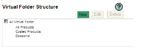
ure
Virtual folders can be created to use in Source. They are groupings of multiple folders across product structures so sourcing plans can be made in a broader or different scope on these folders.
Folder Properties information is used by calculations located in the Planning section of the Line Optimizer Business Plan’s Size Category Sub-Plan so planning numbers need only be entered for the main size category. The business plan will calculate the non-main size category numbers based on the percentage to the main size entered here and the actual planning numbers entered in the plan for the main size.
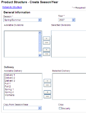
Figure41 The Create Season/Year window
1 From the Administration Business Process Management page, click the Products link. TheProduct Structure page appears with the product structure displayed.
Tip
To add Seasons/Years to any other Fashion PLM structure, click the appropriate Fashion PLM module link in the Structures section (Fabric, Trim, Workflow etc.).
2 Click New. The Create Season/Year page appears.
3 Select a Season from the list. This field is required.
4 Select the Year from the list. This field is required.
5 Select one or more divisions from the Available Divisions list that should have their division-filtered items available in this structure, then click > to move it to the Selected Divisions list.
Tip
Divisions are typically assigned to the structure at a level below the season/year unless the seasons or years have been named as divisons in the Data Dictionary.
6 Select one or more deliveries applicable to the season being created from the Available Delivery list , then click > to move it to the Selected Delivery list.
Tip
Deliveries should be assigned at the Season/Year level. Additional deliveries cannot be added at lower levels, but those assigned at the Season/Year level can be removed at lower levels to which they do not apply.
7 You may select an existing Season/Year from the Copy from Season/Year list to copy its entire folder tree, or leave this field blank to begin a completely new folder structure below.
8 Click the Copy Security check box to also copy the security of the selected Season/Year’s structure. This will copy all assigned Divisions, Deliveries, Item types, Users and Business Partner Locations and Roles and Notification Options assigned to the structure being copied into the new Season/Year structure.
9 Click Save. The new Season/Year appears in the structure.
1 From the Product Structure page, select the desired season/year.
Tip
To edit Seasons/Years of the Fabric, Trim, Workflow, or Line Optimizer structures, click the appropriate link in the Structures section.
2 Click Edit. The Edit Season/Year page appears.
3 Modify the information.
Caution
See “Filtering Rules” on page 17 for important information on filters before adding and removing Divisions on structures.
4 Click Save. The modified Season/Year appears in the structure.
page
1 From the Product Structure page, select the desired folder.
Tip
To add folders to any other Fashion PLM structure, click the appropriate Fashion PLM module link (Fabric, Trim, Workflow etc.) in the Structures section.
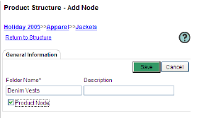
2 Click New. The Add Node page appears.
3 Type the name of this folder in the Folder Name field. This field is required.
4 Enter a Description for this folder.
5 Select the Product Node check box if this folder is the product folder.
Caution
Selecting the Product Node check box will disable the function to add other folders below this level.
6 Click Save. The page refreshes and the Security and Properties tab appear.
7 From the Division section, select a division from the Available Divisions list that should have access to the folder, then click > to move it to the Selected Divisions list.
Caution
See “Filtering Rules” on page 17 for important information on filters before removing Division filters.
8 From the Delivery section, select a delivery from the Available Delivery list, then click > to move it to the Selected Delivery list.
Tip
Deliveries should be assigned at the Season/Year level. Additional deliveries cannot be added at lower levels, but those assigned at the Season/Year level can be removed at lower levels to which they do not apply.
9 Select an Item Type from the Available Item Types list, then click > to move it to the Selected Item Types list.
10 Click the Security tab to add Folder Access. See “Adding Folder Security Information” on page 45 for details.
11 Click the Properties tab to add Line Optimizer mark up and Size catagory information. This tab is only available on the Product structure. See “Adding Folder Properties Information” on page 49 for details.
12 Click Save.
Note
Not all structures have Deliveries and Item Type assignments.
page
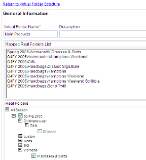
1 From the Product Structure page, click the Virtual Folder link. The Virtual Folder Structure appears.
Note
Virtual Folders are used with Source.
2 Click New. The folder General Information page appears.
3 Type the name of this folder in the Virtual Folder Name field. This field is required.
4 Enter a Description for this folder.
5 Click Save. The Product Manager folder structure appears in the Real Folders list.
6 Select the folders you wish to map by clicking the desired product folders.
Tip
If you select the Season/Year folder, all sub-folders are automatically selected. You can also select only sub-folders.
7 Click Save. The mapped folders appear in Mapped Real Folders List.
Assigning Team Users to a Folder Structure
The Folder Access section
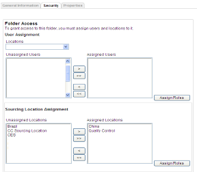
1 From the Product Structure - Edit Node page, click the Security tab. The Folder Access page opens (Figure 34).
2 Select a Location from the list in the User Assignment section. All unassigned Users for the Location appear in Unassigned Users list.
Tip
You may select a different Location from the list. The associated list of users appears for each selected location.
a Click the names of users who should have access to this folder in the Unassigned Users, then click > to move them to the Assigned Users list.
b Select a user in the Assigned Users list, then click Assign Roles. If the selected user has only one role assigned in their User Details, then that role is automatically assigned to them on this structure and the page simply refreshes. All other selected users with one role will also be assigned. If the user has multiple roles or was previously assigned, the Assign Roles window opens and displays the available roles for the selected user in the Unassigned Roles box. (Figure 35).
Figure45 The Assign Roles - Users window
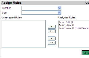
c Select a role that the user should have in this structure from the Unassigned Roles list, then click > to move it to the Assigned Roles list.
d Click Save.
e You may select another user from the User list and assign roles for them.
f Click Save.
g Repeat for all users in all locations.
h Click the Close Window link.
Warning
All users added to the Assigned Users box that have multiple roles in their User Details will not be assigned to the structure unless you assign a role to each of them in the Assign Roles Popup window.
Note
If multiple roles are assigned to a user on one structure, the least-restrictive privileges in all roles take precedence.
Assigning Sourcing Locations to a Folder Structure
1 From the Sourcing Location Assignment section, select one or more sourcing locations who should have access to the folder from the Unassigned Locations list, then click > to move them to the Assigned Locations list.
Figure46 The Assign Roles - Sourcing Location window
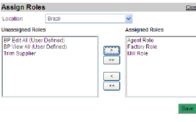
a Select a location in the Assigned Locations list, then click Assign Roles. If the selected location has only one role assigned in its Location Details, then that role is automatically assigned to it on this structure and the page simply refreshes. All other selected locations with one role will also be assigned. If the location has multiple roles or was previously assigned, the Assign Roles window opens and displays the available roles for the selected location in the Unassigned Roles box (Figure 36).
b Select the roles that the location should have from the Unassigned Roles list, then click > to move them to the Assigned Roles list.
c Click Save.
d You may select a different Location from the list and assign Roles to it.
e Click Save.
f Repeat for all locations.
g Click the Close Window link.
Warning
All locations added to the Assigned Users box that have multiple roles in their Location Details will not be assigned to the structure unless you assign a role to each of them in the Assign Roles Popup window.
Note
If multiple roles are assigned to a location on one structure, the least-restrictive privileges in all roles take precedence.
Note
When a user releases a product to a Sourcing Location in Product Manager or Line Optimizer, they may select one or more of the roles the location has associated on the structure to assign to the location for the product. If multiple roles are selected by the user, the least-restrictive privileges in all roles take precedence.
Assigning Business Partner Locations to a Folder Structure
1 From the Business Partner Assignment section, select a company name from the Business Partners list. All unassigned locations for the business partner company appear in the Unassigned Locations list.
2 Select one or more locations who should have access to the folder from the Unassigned Locations list, then click > to move them to the Assigned Locations list
Figure47 The Assign Roles - Business Partner Location window
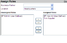
a Select a location in the Assigned Locations list, then click Assign Roles. If the selected location has only one role assigned in its Location Details, then that role is automatically assigned to it on this structure and the page simply refreshes. All other selected locations with one role will also be assigned. If the location has multiple roles or was previously assigned, the Assign Roles window opens and displays the available roles for the selected location in the Unassigned Roles box (Figure 37).
b Select the roles that the location should have from the Unassigned Roles list, then click > to move them to the Assigned Roles list.
c Click Save.
d You may select a different Location for the same Business Partner from the list and assign Roles to it.
e Click Save.
f You may select another Business Partner from the list and a Location and assign Roles to it.
g Click Save.
h Repeat for all locations you wish to assign.
i Click the Close Window link.
Warning
All locations added to the Assigned Users box that have multiple roles in their Location Details will not be assigned to the structure unless you assign a role to each of them in the Assign Roles Popup window.
Note
If multiple roles are assigned to a location on one structure, the least-restrictive privileges in all roles take precedence.
Note
When a user releases a product to a Business Partner Location in Product Manager or Line Optimizer, they may select one or more of the roles the location has associated on the structure to assign to the location for the product. If multiple roles are selected by the user, the least-restrictive privileges in all roles take precedence
Adding Folder Properties Information
The Properties tab
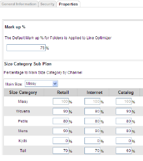
1 From the Product Structure - Edit Node page, click the Properties tab. The Mark up % and Size Category Sub Plan sections appear (Figure 38).
2 From the Mark up % section, enter a default mark up percentage for the folder in the field. This percentage will be applied in Line Optimizer.
3 From the Size Category Sub Plan section, select a Size Category from the Main Size list. The associated channels are listed per Size Category.
4 Enter the percentage to the main size category for each channel in the respective fields.
Note
There is no need add the % symbol. It is applied automatically.
5 Click Save.
1 From the Product Structure page, select the desired folder.
Tip
To edit a folder from any other Fashion PLM structure, click the appropriate Fashion PLM module link (Fabric, Trim, Workflow etc.).
2 Click Edit. The Edit Node page appears.
3 Modify the information.
4 Click Save.
Figure49 T
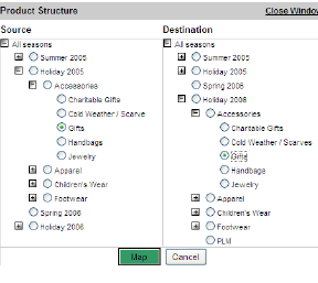
he Map Product Structure window
1 From the Product Structure page, click Action>Map. The Map Product Structure opens in a separate window.
Note
Mapping the financial data applies to Line Optimizer this option is accessible only from the Product Structure.
2 Select the folder you wish to map from the Source structure.
3 Select the folder you to which you wish to map the financial data from the Destination structure.
Caution
You can only map information for the same season in consequtive years and folders with the same names and sub-folders.
4 Click Map. A successful message appears.
5 Click OK.
1 From the Product Structure page, select the desired folder.
Tip
To delete a folder from any other Fashion PLM structure, click the appropriate Fashion PLM module link (Fabric, Trim, Workflow etc.)..
2 Click Delete. A delete confirmation appears.
3 Click OK. The folder is deleted.
The Security section of Business Process Management is where Roles are created and defined.
Roles define access privileges such as the ability to create and delete items in each Fashion PLM module. These are yes/no privileges for each module. Roles also define edit privileges (None, View, Edit) on the forms used on items in each module, to the section and in some instances, the field level.
The three levels of access you may grant to a Role on form sections are defined as follows:
a None (no access - invisible in the form or folder structure)
b View (read-only)
c Edit (modify and delete fields within a section or items in the structure)
Figure50 The Roles list
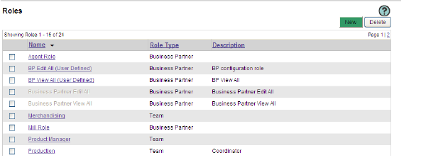
Roles are assigned to users, Sourcing Locations and Business Partner Locations as they are given access to the folder Structures. This is the second level of access for users and business partners within Fashion PLM. The first level of access is Module Assignment, which is given to master company users in their User Details, and to business partner companies in their Company Details.
Roles are associated to each team user; and from those, one or more roles are assigned to users as they are given access to folder structures. Therefore, it is possible for users to have different roles on different folder structures.
Roles are assigned to the Master Company’s Sourcing Locations, and finally to the locations as they are given access to folder structures. All team users associated to a Sourcing Location share the same level of access since it is their locations that are assigned to the structure and assigned a Role. They too can have different roles on different structures.
For Business Partners, roles are assigned to the Business Partner Company, then each of its Locations, and finally to the locations as they are given access to folder structures. All users associated to a Business Partner Location share the same level of access since it is their locations that are assigned to the structure and assigned a Role. They too can have different roles on different structures.
It is possible to assign users, sourcing and business partner locations multiple Roles on the same structure- at the same level or different levels. All role privileges trickle down through the structure and the most permissive privileges from all roles assigned to the structure dictate each user’s and location’s access.
Product Manager and Line Optimizer provide an additional level of role assignment beyond the structure, whereby when a user releases a product to a Sourcing or Business Partner Location, the user may select one or more of the roles the location has on the structure to assign to the location for that product. If multiple roles are selected by the user, the least-restrictive privileges in all roles take precedence.
Channel and Size Category privileges control access on the Planning tables on the Planning form on products and in the Business and Attribute Plan tables.
Item ID and Retail Price by size category privileges control edit capability to these fields on the Product Overview form.
1 From the Administration Business Process Management tab, click the Roles link in the Security section. The existing roles in Product Manager are listed.
2 Click Actions>New to add a new role. The Role Details page opens.
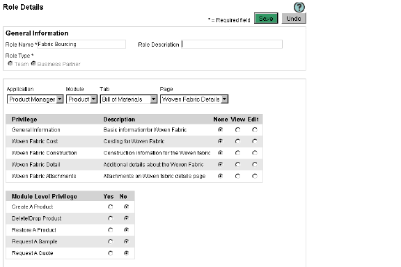
Figure51 The Role Details page
Tip
You may also click New to add a new role.
3 Enter details in the General Information section:
a Type a Role Name in the field. This is a required field.
b Enter a Role Description in the field.
c Select a Role Type for the new role. This is a required field.
Note
If a Role is assigned the Business Partner Role Type, the role will only be available for Business Partners.
Note
The Role Type field locks when a new role is saved.
4 Select an Application from the list.
5 Select a Module for the selected application from the list.
6 Select a Tab for the selected module.
7 Select a Page for the selected module.
Note
The Privileges will be different depending on the Module, Tab, and Page selected.
Figure52 Role Security for Modules
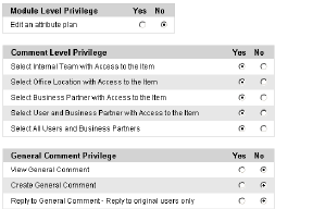
8 Add Privileges for this role by clicking the appropriate radio button for each item (Figure 42).
9 From the Module Level Privilege section, select Yes or No for each listed item.
10 From the Comment Level Privilege section, select Yes or No for each listed item.
11 From the General Comment Privilege section, select Yes or No for each listed item.
Note
For Line Optimizer roles, you will need to specify access levels for Channels and Size Categories. See “Assigning Channel and Size Category Privileges” below for details.
12 Add security for every Application, Module, Tab, and Page.
13 Click Save. The added role is listed alphabetically on the Roles page.
Assigning Channel and Size Category Privileges
Figure53 The Line Optimizer Role Security s
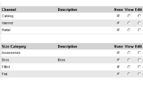
ection
1 From the Roles Details page for the Line Optimizer module (Figure 43), select a level of privilege for each listed Channel.
2 Select a level of privilege for each listed Size Category.
3 Click Save.
1 From the Roles page, click the desired role name. The Role Details page opens (Figure 41).
2 Modify the role information.
3 Click Save. The Role Details page is closed and the list of roles appears.
Caution
System-defined roles cannot be edited, except for the Costing role. See “System-Defined Roles” on page 56.
1 From the Roles page, click the check box to the left of the role you wish to copy.
2 Click Actions>Copy. A confirmation message appears.
Caution
You may not change the role type of a copied role.
3 Click OK. The Role is copied and identified as “Copy of...”. If a copy already exists, copy (1) will be created.
1 From the Roles page, click the check box to the left of the role(s) you wish to delete.
2 Click Actions>Delete. A confirmation message appears.
Caution
System-defined roles cannot be deleted. See “System-Defined Roles” on page 56.
3 Click OK. The role is deleted.
Warning
This action may not be undone and the role will be permanently deleted.
To help make role definition easier, System-Defined Roles are provided. They have pre-defined privilege settings. Some can be edited and some are and locked. You can assign these roles to users and locations. You can also copy them as efficient starting points for new roles.
The following System-Defined Roles are provided to use for Master Company Sourcing Locations and Business Partners:
• Business Partner Edit All - has Edit privileges on all modules’ form sections, Yes enabled on many module level privileges, No general comment privileges and View on the Line Optimizer Channel and Size Category planning fields. This role cannot be edited but can be copied.
• Business Partner Edit All (User Defined) - is a copy of Business Partner Edit All that can be edited and copied.
• Business Partner View All - has View privileges on all modules’ form sections, No module level privileges, No general comment privileges and View on the Line Optimizer Channel and Size Category planning fields. This role cannot be edited but can be copied.
• Business Partner View All (User Defined) - is a copy of Business Partner View All that can be edited and copied.
• Costing Role - is automatically assigned to any BPs when a cost request is done in PM or FT - it uses the security from that role to give the BP access to the item even if the item was not released. It is pre-defined with View privileges to the core spec pages only. This role can be edited and copied, but cannot be deleted.
The following System-Defined Roles are provided to use for Team Users:
• Team Administrator - Full create, delete and edit privileges in all modules and forms. This role is automatically assigned to users that are given Team Administrator User Access in their User Details. and cannot be edited, copied or deleted.
Note
As part of their User Access assignment Team administrators also have a deep level of administrative abilities and full visibility to all items, projects and comments in the structures to which they are assigned.
• Team Edit All - has Edit privileges on all modules’ form sections, Yes enabled on many module level privileges, No general comment privileges and View on the Line Optimizer Channel and Size Category planning fields. This role cannot be edited but can be copied.
• Team Edit All (User Defined) - is a copy of Team Edit All that can be edited and copied.
• Team View All - has View privileges on all modules’ form sections, No module level privileges, No general comment privileges and View on the Line Optimizer Channel and Size Category planning fields. This role cannot be edited but can be copied.
• Team View All (User Defined) - is a copy of Team View All that can be edited and copied.
Note
When new sections or forms are added to our applications, the System-Defined Roles are automatically updated and set as edit or view for all new sections and pages in accordance with the role.
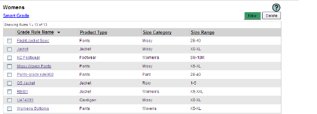
The Smart Grade section of the Business Process Management is a critical part of product specifications. You can create, store and modify corporate grade rules for each possible combination of Product Type, Size Category, and Size Range.
Figure54 The Smart Grade folder view
Each Grade rule must be associated to one Product Type, Size Category and Size Range, therefore, these must be defined in the Data Dictionary prior to creating Grade Rules.
All Points of Measure must be added to the Manage POMs list and sorted before Grade Rules can be defined. Each is associated to Product Types and this association filters the POM that will be available to add to a Grade Rule for a particular Product Type. See “Manage POMs” on page 144
When Points of Measure are added to a grade rule, each is prioritized. The options are:
• Mandatory POM must be on every product using the grade rule and will be locked in the Specification Table. They cannot be removed and their Codes and Descriptions cannot be edited.
• Default POM are initially included in the Measurement Table with the Mandatory POM when the grade rule is added to a product, but can be edited and removed.
• Optional POM are not initially added to a product when the grade rule is added, however they are made available in the Add POMs list so any may be added to the product as needed. They are also editable and can be removed again.
Grade increments and tolerances are typed into the Grade Rule Table for each size in the size range. The increments can be entered in one of three Grade Rule Formats.
There are three grade rule formats available in Product Manager. They are:
• Relative: Grade increments are relative to the size adjacent and a sample size is used as the base size. Any increments for sizes smaller than the sample size must have minus (-) preceding them.
• Incremental: Grade increments are relative to the size adjacent and the smallest size is used as the base. There are no minus (-) in this format.
• Absolute: Grade increments are entered and viewed absolute to the selected sample size, therefore, the grade increments are exponential. Any increments for sizes smaller than the sample size must have minus (-) preceding them.
The grading is calculated the same regardless of which method is used to enter the grade rules. Grade rules are stored in the database in the Incremental format.
Users also have the option to define their own default view between Incremental, Relative, and Absolute in their User Profiles. The format selected in the Company profile is used as a default for new users as they are created.
Any sample size may be selected on products regardless of the sample size used in the grade rule because of the intelligence built into Smart Grade.
Any sub-set of the sizes within the grade rules’s size range may be selected on products, therefore you will not need grade rules for all possible size range sub-sets.
Once on the Product Specification pages, you will be able to select one Grade Rule per Specification page and all associated information will automatically be loaded into the page.
1 From the Administration Business Process Management tab, click the Smart Grade link. The Smart Grade Structure page opens.You may also click the New button.
2 Select a Smart Grade folder. The list of Grade Rules appears.
Figure55 The New Grade Rule window
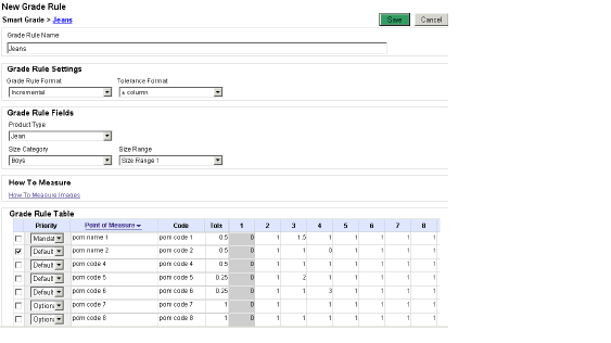
3 Click Actions>Grade Rule>New. The New Grade Rule window opens.
Tip
You may also click the New button.
4 Type the Grade Rule Name.
5 Select the Grade Rule Format from the list. This will dictate how the grade rules must be entered into the Grade Rule Table. See “Grade Rule Format” on page 59.
6 Select the Tolerance Format from the list.
Note
The +/- column will list tolerance levels in the same column. For non-identical +/- tolerances, select the + and - columns option.
7 Select the Product Type from the list. Associated Size Categories are filtered.
8 Select the Size Category from the list. Associated Size Ranges are filtered.
9 Select the Size Range from the list.
10 If you have selected the Relative or Absolute Grade Rule format, select the Sample Size.
11 Add Points of Measures for the selected Product Type, Size Category, Size Range, and Sample Size and set POM Defaults. See “Adding Points of Measure” on page 61 for details.
12 Add Grades differentials for each POM per size.
Tip
Leave a grade empty if you do not wish for it to be calculated.
13 Click Save.
Figure56 The Add Points of Measure window
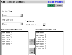
1 From the Grade Rule page, click Actions>Point of Measure>Add. The Add Points of Measure window opens (Figure 46).
2 The Product Type, Size Category, Size Range, and Sample Size are selected and locked. The associated Points of Measure for the selection are listed in the Available Points of Measure.
3 Select Points of Measure from the Available Points of Measure list and click > to move them to the Selected Points of Measure.
4 Click Save.
1 From the Grade Rule page, select the POM you wish to replace.
Figure57 The Replace Points of Measure window
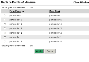
2 Click Actions>Point of Measure>Replace. The Replace Points of Measure window opens (Figure 47).
3 Select the desired POM radio button.
4 Click Apply. The selected POM is replaced but the grade increments and priority are kept.
1 From the Grade Rule page, select the POM(s) for which you wish to set a priority.
2 Click Actions>Point of Measure>Set Priority
• Mandatory POM must be on every product using the grade rule and will be locked in the Specification Table. They cannot be removed and their Codes and Descriptions cannot be edited.
• Default POM are initially included in the Measurement Table with the Mandatory POM when the grade rule is added to a product, but can be edited and removed.
• Optional POM are not initially added to a product when the grade rule is added, however they are made available in the Add POMs list so any may be added to the product as needed. They are also editable and can be removed again.
Tip
You may also select the POM priority from the Priority list.
3 Click Save.
Figure58 The Additional How to Measure Images window
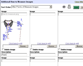
1 From the Graded Measurement page, click Action>Add How to Measure Images. The Additional How to Measure Images window opens.
2 Select a Sort Order from the list.
3 Click Browse to navigate to your folder and select the desired file.
Tip
You may also add template images. See “Adding an Image Template” below.
4 Click Open. The image appears.
Caution
If the selected image is a Designer drawing, you will need to select the Designer view.
5 Type a Description for the POM and how to measure it.
6 Repeat for other images.
7 Click Save, then click the Close Window link to exit.
Note
The image is visible when clicking the How to Measure Images link.
8 Click Save to save the Grade Rule modifications.
1 From the Additional Images window, click the Library![]() icon located next to the Save button. The Template Structure window opens. Only the folders you have access to appear in the Library Structure.
icon located next to the Save button. The Template Structure window opens. Only the folders you have access to appear in the Library Structure.
2 Select a template folder or use the Quick Search to locate the desired template. The Select Template page appears.
Tip
Click the Return to Template Structure link to continue navigating for a template.
3 Select a template, then click on Select or Select & Link. The image template appears on the page.
Caution
If the selected image is a Designer drawing, you will need to select the Designer view.
Tip
You may also add template images. See “Adding a HTM Template” below.
4 Type a Description for the POM and how to measure it.
5 Repeat for other images.
6 Click Save, then click the Close Window link to exit.
1 From the Additional Images window, click the Library icon located next to the Save button. The Template Structure window opens. Only the folders you have access to appear in the Library Structure.
2 Select a template folder or use the Quick Search to locate the desired template. The Select Template page appears.
Tip
Click the Return to Template Structure link to continue navigating for a template.
3 Select a template, then click on Select or Select & Link. The image template appears on the page.
4 Click Save, then click the Close Window link to exit.

Sort Points of Measure window
1 From the Grade Rule page, click Actions>Point of Measure>Sort>User Defined Sort Order. The Sort Points of Measure window opens.
2 Select a POM and use the arrows to move it up or down.
Tip
The Point of Measure and Code hyper links allow you to sort the lists in ascending or descending order by Description or Code.
3 Click Save. The sort order is saved on the grade rule.
Tip
You may also sort POMs by the order in which they were sorted by the Administrator by clicking Actions>Point of Measure>Sort>Data Dictionary Sort Order.
4 Click Close Window. The POM list is sorted.
1 From the Grade Rule page, select the POM(s) to be deleted.
2 Click Actions>Point of Measure>Delete. The selected POM(s) is deleted.
3 Click Save. The page refreshes and the change is saved.
Warning
This action may not be undone and the POM will be permanently deleted.
1 From the Edit Grade Rule page, click Action>Grade Rule and click Copy. The Smart Grade Structure window opens.
2 Navigate the structure, clicking the + icons to expand it.
3 Select a grade node folder and click Copy. A confirmation appears in the window.
4 Click Close Window. The Grade Structure window closes, the page refreshes and the new copy opens. The Grade Rule Name is prefixed with “Copy of” and may be changed.
1 From the Edit Grade Rule page, click Action>Grade Rule and click Delete. A confirmation prompt opens.
2 Click OK. The prompt closes and the page refreshes to the SmartGrade folder.
You can create, store and modify corporate Operation Lists for each Product Type. The Operation List section allows you to enter labor time and cost information for sewing or pressing tasks that factor into the overall cost of your product.
When adding operations you can specify the labor cost per operation or define an average labor cost.
Each Operation List must be associated to one Product Type, therefore, these must be defined in the Data Dictionary prior to creating Operation Lists.
All Operations must be added to the Manage Operations list and sorted before Operation Lists can be defined. Each is associated to Product Types and this association filters the Operations that will be available to add to an Operation List for a particular Product Type. See “Manage Operations” on page 147
When Operations are added to an Operation List, each is prioritized. The options are:
• Mandatory Operations must be on every product using the Operation List and will be locked in the Operation Table. They cannot be removed and their Codes and Descriptions cannot be edited.
• Default Operations are initially included in the Operation Table with the Mandatory Operations when the Operation List is added to a product, but can be edited and removed.
• Optional Operations are not initially added to a product when the Operation List is added, however they are made available in the Add Operations list so any may be added to the product as needed. They are also editable and can be removed again.
Viewing and Editing Operation Lists
1 From the Administration Business Process Management tab, click the Operation List link in the Operation List section. The Operation List Structure page opens.
2 Select a folder. The Operation List Manager page opens (Figure 50).
Figure60 The Operation List Manager page
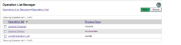
3 Select an Operation List link to open the Edit Operation List window.
4 Modify the operation.
5 Click Save. The Operation list appears.
1 From the Operation List Manager page, click Action>New. The New Operation List page opens (Figure 51).
Figure61 The New Operation List page

2 Enter an Operation Name in the field. This field is required.
3 Select a Product Type from the list. This field is required.
Figure62 The Add Operation window

4 Enter an Average Labor Rate in the field. This will be used as the Labor Rate for any Operations that do not have a Labor Rate associated to them in Manage Operations.
5 Click Action>Operation>Add to open the Add Operation window. All operations for the selected Product Type are listed in the Available Operation list.
Caution
You may not save an Operation List without adding operations to the Operations Table. You will need to define operations before creating your lists. See “Adding New Operations” on page 148 for details.
6 Select an Operation and click > to move it to the Selected Operation list.
7 Click Save. The window closes and the operation is added to the Operation Table.
8 For each operation, select a Priority from the list. See “Defining Operation Priority” below for details.
9 The Standard Allowable Minute and Labor Rate are predefined.You may edit these by scrolling the table to the right and entering new values in the SAM and Labor Rate fields.
10 Click Save.
1 From the Operation Table section of the New/Edit Operation List page, select a Priority from the list.
2 To define the priority of several operations at once, select the check boxes of the operations, then click Action>Operation>Set Priority:
• Mandatory Operations must be on every product using the Operation List and will be locked in the Operation Table. They cannot be removed and their Codes and Descriptions cannot be edited.
• Default Operations are initially included in the Operation Table with the Mandatory Operations when the Operation List is added to a product, but can be edited and removed.
• Optional Operations are not initially added to a product when the Operation List is added, however they are made available in the Add Operations list so any may be added to the product as needed. They are also editable and can be removed again.
3 Click Save. The page refreshes.
1 From the Edit Operation List page, click Action>Operation>Sort and click User Defined. The Set Sort Order window opens.
2 Select an Operation Code and click the arrows to move it up or down.
3 Click Save. The sort order is saved on the Operation List.
Tip
You may also sort Operations by the order in which they were sorted by the Administrator by clicking Actions>Operation>Sort>Data Dictionary.
4 Click Close Window. The Operation list is sorted.
1 From the Edit Operation List page, select the Operation(s) to be deleted.
2 Click Action>Operation and click Delete. The selected Operation(s) is deleted.
3 Click Save. The page refreshes and the change is saved.
Warning
This action may not be undone and the Operation will be permanently deleted.
1 From the Operation List Manager page, select the check boxes of the Operation Lists you wish to copy.
Figure63 The Operation List Structure window
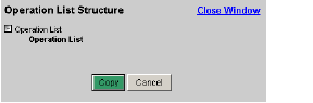
2 Click Action>Copy. The Operation List Structure window opens.
3 Select a folder from the list, then click Copy. The Edit Operation page opens for the new copy.
4 The Operation List Name is prefixed with “Copy of” by default. Enter a new name in the field.
5 Modify the operation as need. See “Creating a List of Operations” on page 67.
6 Click Save.
1 From the Operation List Manager page, select the check boxes of the Operation List(s) you wish to delete.
2 Click Action>Delete. A confirmation prompt opens.
3 Click OK. The prompt closes; the Operation List Manager page refreshes and the Operation List(s) is deleted.
Warning
This action may not be undone and will permanently delete the selected operation(s).
The Variations section allows you to define how you want Line Optimizer to calculate product variations. Since products developed in Product Manager may be calculated in the Line Optimizer, product variations can be counted as part of the parent product or calculated as separate products.
You may define how Line Optimizer will calculate variations by the variation reason selected for Business and Attributes Plans, as well as specify if the variation can be added to a Catalog.
Viewing and Editing Variation Rules
1 From the Administration Business Process Management tab, click the Variation Rule link in the Variation section. The Variation Reason Rules page opens.
Figure64 The Variation Reason Rules page
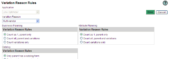
2 You can only define variation rules for Line Optimizer and it is selected and locked in the Application field.
3 Select a Variation Reason from the list. The page is refreshed to display the variation rules.
Note
You may add new variation reasons using the Data Dictionary. See “Manage Fields” on page 135.
4 In the Business Planning section, select the rule appropriate for the variation reason. The identical selection is automatically applied to the Attribute Planning section.
5 Select an option from the Catalog section.
6 Click Save.
Use the Exchange Rates section to manage seasonal currency exchange rates from the Master Company Currency. The Exchange rates are used on BOM items and Cost Scenarios in Source, allowing normalization of component costs to the cost scenario currency, and also calculation of product costs into multiple currencies, supporting global sourcing and distribution needs.
Requests for Quotes (RFQs) and Cost Scenarios cannot be used on a Product in Source until an Exchange Rate table has been created for the Season/Year in which the Product is stored.
Before the first Exchange Rate table is created, dependant Currency UOMs must be associated to their Countries in the Data Dictionary. Only Countries that have a dependant Currency UOM will be available to add to the Exchange Rate tables.
Viewing and Editing Exchange Rates
Figure65 The Exchange Rate Table Manager window
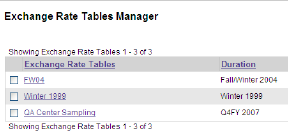
1 From the Administration Business Process Management tab, click the Exchange Rate link in the Exchange Rate section. The Exchange Rate Table Manager page opens.
2 Select a Exchange Rate Tables link to open the Exchange Rate Tables window.
3 Add a Country to the Exchange Rate Table. See “Adding Countries to the Exchange Rate Table” on page 73.
4 Enter a new Exchange Rate in the field.
5 You may also remove or archive countries. See “Removing Countries from the Exchange Rate Table” or “From the New Exchange Rates Table page, select the country you wish to remove from the Exchange Rate Table.” on page 74.
6 Click Save.
1 From the Exchange Rate Table Manager page, click New. The New Exchange Rates Table page opens.
Figure66 The New Exchange Rates Table page
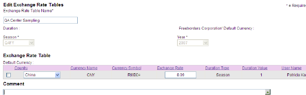
2 Enter a name for this exchange rate in the Exchange Rate Table Name field. This field is required.
3 Define the Duration by selecting a Season from the list. This field is required.
4 Select a Year from the list. This field is required.
5 Add a Country to the Exchange Rate Table. See “Adding Countries to the Exchange Rate Table” on page 73.
6 You may also remove or archive countries. See “Removing Countries from the Exchange Rate Table” or “From the New Exchange Rates Table page, select the country you wish to remove from the Exchange Rate Table.” on page 74.
7 Click Save.
Adding Countries to the Exchange Rate Table
1 From the New Exchange Rates Table page, click Action>Add Country. A new row is added to Exchange Rate Table.
2 Select a Country from the list. The page is refreshed with the Currency Name and Symbol.
3 Enter an Exchange Rate in the field.
4 Click Save.
Note
Only Countries that have a dependant Currency UOM associated to them in the Data Dictionary will be available to add to the Exchange Rate tables.
Removing Countries from the Exchange Rate Table
1 From the New Exchange Rates Table page, select the country you wish to remove from the Exchange Rate Table.
2 Click Action>Remove Country. A confirmation message appears.
3 Click OK. The page refreshes and the country row is removed from the Exchange Rate Table and added to the History section below.
4 Click Save.
Archiving Countries from the Exchange Rate Table
1 From the New Exchange Rates Table page, select the country you wish to archive from the Exchange Rate Table.
Tip
Archive a country when you need to update the active exchange rate for the country so you keep a record of the previous rate in History.
2 Click Action>Archive Country. The country and exchange rate are copied to the History table. The archived countries are in read-only format.
Figure67 The Copy Exchange Rate window
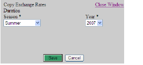
1 From the Exchange Rate Table Manager page, select the check box of the Exchange Rate Table you wish to copy.
2 Click Action>Copy. The Copy Exchange Rate window appears.
3 Select a Season from the list. This field is required.
4 Select a Year from the list. This field is required.
5 Click Save. The selected exchange Rate Table is copied and listed as “Copy of”.
Note
You cannot have more than one Exchange rate Table per Season/Year.
1 From the Exchange Rate Table Manager page, select the check box of the Exchange Rate Table you wish to delete.
2 Click Action>Delete. A confirmation message appears.
3 Click OK. The Exchange Rate Table is deleted.
The Standards section is used with Fabric & Trim and comes loaded with industry standard tests. You may add new tests and create your own Performance standards by grouping selected tests together.
Figure68 The Standards list window
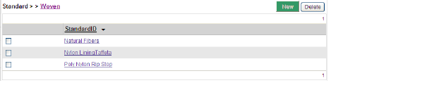
Users will have the option to requests testing from sourcing offices or business partners and the ability to choose which testing Standard to use on the fabric or tim.
Figure69 The Standards Structure window
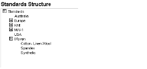
1 From the Administration Business Process Management tab, click the Fabric or Trim link in the Standards section. The Standards Structure window opens.
2 Select a folder. All existing standards are listed.
3 Select a Standard ID to open the standard. The Edit Standard page opens.
4 Modify the Name and Description.
5 Add, delete or sort the tests for this standard.
6 Click Save. The Standard list appears (Figure 56).
1 From the Standard Structure page, select a Standard folder. The list of Standards appears.
2 Click Action>New. The New Standard page opens (Figure 43).
Figure70 The New Standard page
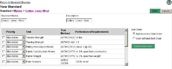
3 Type the Standard Name in the field.
4 Type a Description in the field.
Figure71 The Add Test window
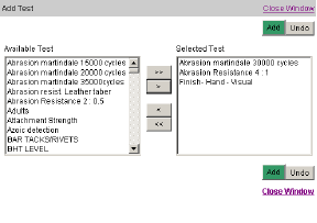
5 Click Action>Tests>Add. The Add Test window opens (Figure 60).
6 Select tests from the Available Tests list and click > to move them to the Selected Tests.
7 Click Add. The window closes and selected tests are listed with the Priority Optional.
8 Select a Mandatory, Default, or Optional Priority for all listed tests:
• Mandatory - The test will appear by default on the list of tests on the Performance Standard page. It will be locked and can not be edited or removed.
• Default - The test will appear by default on the list of tests on the Performance Standard page. It can be edited or removed.
• Optional - The test will not appear by default on the list of tests on the Performance Standard page. It will need to be added by the user.
9 Type the Performance Requirements for each Test.
10 Click Save. The list of Standards appears.
Figure72 The Set Sort Order window

1 From the Standard page, select the User-Defined Sort Order radio button.
2 Click the Define Sort Order button. The Set Sort Order window opens (Figure 61).
3 Select an item and use the arrows to move it up or down.
4 Click Apply. The list is sorted as selected.
Sorting Tests Alphanumerically
Figure73 The Sort Order section

1 From the Standard page, select the Alphanumeric Sort Order radio button (Figure 62).
2 Click the Action>Test>Sort. The list is reordered alphanumerically.
1 From the Standard page, select the check box of the test you wish to remove.
2 Click Actions>Test>Delete. The selected test is deleted.
1 From the Edit Standard page click Action>Standard and click Copy. The Standard Structure window opens.
2 Navigate the structure, clicking the + icons to expand it.
3 Select a standard node folder and click Copy. A confirmation appears in the window.
4 Click Close Window. The Standard Structure window closes, the page refreshes and the original standard remains open.
5 Click the fabric or Trim link in the Standards section at the left side of the screen, and navigate to the location to which the new copy was saved. The copy’s name is prefixed with “Copy of” and may be changed in its Edit Standard page.
1 From the Edit Standard page, click Action>Standard and click Delete. A confirmation prompt opens.
2 Click OK. The prompt closes and the page refreshes to the Standard folder.
1 From the Administration Home page, click the Manage Tests link in the Standards section. The Manage Tests window opens (Figure 74).
Figure74 The Manage Test window
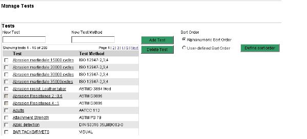
2 Type a New Test name in the field.
3 Type the New Test Method for the test.
4 Click Add Test. The test is added at the bottom of the list.
Tip
You may need to navigate to a different page to view the whole list of tests.
5 Select a sort option for your tests. See “Removing Tests from Standards” on page 92.
1 From the Manage Test page, select the check box of the test you wish to delete.
2 Click Delete Test. The selected test is deleted.
The Configuration section of the Administration module allows you to set up your blank base form, configure blanks and standard forms, form sets, items types, print templates, print sets, and shortcuts to third party reports.
Configurable forms are variations of our Blank and Standard Forms that you may design for your company’s specific needs. They provide the flexibility to change field names, size, and positions. Add or hide fields, while maintaining the access levels defined for the forms in the company Roles. The Blank form is the one Base Form that allows you to define its Tab and Section names and is currently available for Product Manager products. Different variations of the same form may be created for various divisions.
Item Types are a combination of item information, Templates and Form Set. A Form Set is a predefined group of forms. Either or both can be selected while creating a new item in Fabric & Trim, Line Optimizer and Product Manager, and saves your users the extra steps of adding forms and templates individually to them.
You may create variations of the blank and standard forms, although their base forms may not be edited or deleted. The Blank form is the only base form on which the Tab and Section names may be configured.
You may create User Fields to add to your form variations, you may hide fields and sections of these forms, change the form layout, or the name and appearance of fields. Use the Manage Fields features to create new list items as well as control dependencies between fields. See “Data Dictionary” on page 135 for details.
You may control access to the form variations by filtering by Divisions. This allows you to control the product forms with which the various businesses in your company can work.
In the Standard Forms section, you may define the tab name and section names for the Product Manager Blank form. When modified in the Administration module, it is updated in a spec packages. Create a variation of the Blank Form and configure its content and layout.
In order to be able to use the Form Designer you will add the URL to your list of secured sites, and set your browser to download and run Active X components.
Only Administrators can create form variations and associate them to Divisions. Likewise, only Administrators can create Item Type, Forms Sets, Print Set and Print Templates.
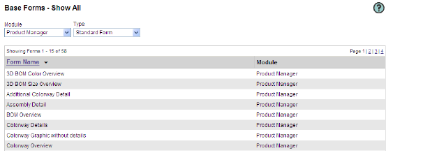
1 From the Administration Business Process Management tab, click a form link in the Configuration section:
• Base Forms - lists all system-defined Blank and Standard Forms by module. Only the Product Manager Blank Form may be opened and edited in this section.
• Configurable Forms - lists all user-defined form variations of the Blank and Standard Forms by module.
2 The appropriate Forms list appears.
The Base Forms list
3 Select a Module from the list.
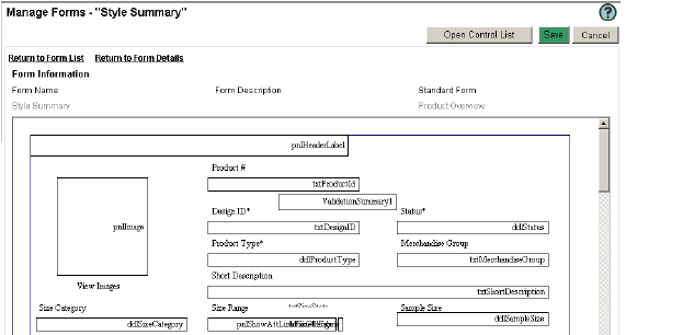
4 Click the Form Name link of a form in the list. The Manage Form window opens.
Note
You can only open the Blank Form in the Base Forms section.
5 Standard Base Forms may not be modified. You can create a configurable form based on a standard or Blank Base Form. See “Creating Form Variations” on page 82.
6 Modify the information, then click Save.
1 Click the column header to sort the list in ascending order by the selected column.
2 Click the same header again to sort the list in descending order.
3 Click a different column header to sort by a different column in ascending order.
1 From the Base Forms- Show All list, select Product Manager from the Module dropdown. The Type dropdown default selection is Blank Form, so the Blank form will appear in the list below.
2 Click the Blank Form name. The Blank Form Details opens.
3 Highlight the default Tab Name and type a new name. This will be used on all variations of the Blank Form for your company.
4 Highlight the Section 1 name and type a new name. This will be used on all variations of the Blank Form that have section 1 visible.
5 You may type a Description for each section name. This is for the administrators reference.
6 Repeat steps 4 and 5 for all sections.
7 Click Save. The page refreshes and the changes are saved and appear on all products using the Blank Form.
1 From the Configurable Forms list, select the forms you wish to copy.
2 Click Actions>Copy. A confirmation message appears.
3 Click OK. The form is copied and identified as “Copy of...”.
1 From the Configurable Forms list page, select a Module from the dropdown. The list of available forms appears.
Note
You may create variations of the Product Manager, Line Optimizer, Storyboard, Source and Fabric & Trim standard forms.
2 Click Actions>New Form. The Manage Form - New Form window opens.
Figure76 The Manage Form - New Form window
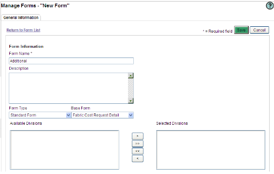
3 Type a Form Name in the field. The Form Name is a required field and must be unique.
4 Type a Description in the field.
5 Select a Form Type from the list. This field will lock when the new variation is saved.
Note
The Form Type field is editable only for Product Manager Forms as you may select between the Blank and Standard Forms for this module.
6 Select a Base Form from the list. This field will lock when the new variation is saved.
7 Select a Division from the Available Divisions list, then click > to move it to the Selected Divisions list. This form will be available only to selected Divisions.
Note
If a Division is not selected, the form will be available for all Form Sets and in all folders.
Caution
See “Filtering Rules” on page 19 for important information on filters before removing Division filters.
8 Click Save. The Logo and Copyright sections appear.
9 Select the logo used for this form from the Logo Selection list.
10 Select the copyright information from the Copyright Selection list.
Note
By selecting a logo and copyright you will make them available to add to the form variation in the Form Designer.
11 Use the Form Designer to customize the form content and layout. See “Using the Form Designer” below.
12 Click Save.
1 From the Form Details page, click the Form Designer button. The Form Designer page opens.
Caution
You may be prompted to download the Active X component. If you are having difficulty viewing this page, add it to your secure sites.
Figure77 The Form Designer page
2 Change the form properties.
3 Modify existing fields:
• Showing Form Gridlines
• Hiding Form Gridlines
• Selecting a Section Background Color
• Showing/Hiding a Section
• Setting the Section Property
• Setting Field Properties
• Setting Label Properties
• Resizing Objects Visually
• Aligning Objects
• Nudging Objects
• Applying Staircasing
• Moving a Field to a Different Section
Tip
See the following for details on these functions.
Figure78 The Select Controls window
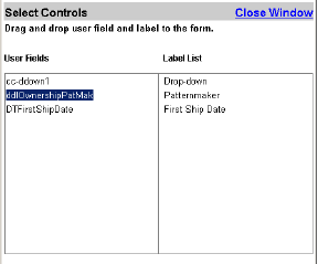
4 Click Actions>Open Control List. The Select Controls window appears. This shows all user defined fields that were associated to the form but have not been added yet.
Tip
You may also click the Open Control List button to open the Select Controls window.
5 Click and drag the Logo onto the form in the appropriate section.
6 Click and drag the Copyright onto the form in the appropriate section.
7 Click and drag User Fields onto the form in the appropriate section.
8 Click and drag the label from the Label List onto the form next to or above the User Field.
Tip
Use Action>Undo/Redo to undo or redo actions while using the Form Designer.
9 Click the Open Standard Control List button. The Select Controls window opens and shows any standard fields and labels that have previously been hidden on the form and any new standard fields that were added to the form in an upgraded version.
10 Click and drag Standard Fields onto the form in the appropriate section.
11 Click and drag the label from the Label List onto the form next to or above the Standard Field.
12 Click Save. The form is modified.
1 Right-click on the form and select Show Gridlines from the shortcut menu. The gridlines appear. The Snap to Grid feature will be enabled by default and helps align fields to the grid while dragging them.
2 Right-click on the form and select Snap to Grid to disable this feature.
3 Repeat step 3 to re-enable the Snap to Grid feature.
4 Right-click on the form and select Hide Gridlines. The gridlines will disappear and Snap to Grid is disabled.
Selecting a Section Background Color
Figure79 The Background Color window

1 From the Form Design window, right-click a blank space on a section and select Background Color from the shortcut menu. The Background Color window appears (Figure 69).
2 Select a predefined color from the Color list or click Color Picker to select a custom color.
3 Click Apply. The section background color changes.
Figure80 The Show/Hide Sections window
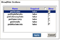
1 From the Form Design window, right-click a blank space on a section and select Show/Hide Sections from the shortcut menu. The Show/Hide Sections window appears (Figure 70).
2 Select the Show check box of the section(s) you wish to render visible. Uncheck a section to hide it.
Caution
You may only hide sections that do not contain required fields. Sections that cannot be hidden are listed as True in the Required column.
3 Click Apply. The section is shown/hidden.
Figure81 The Section Property window
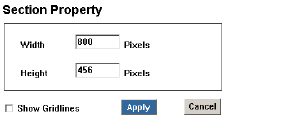
1 From the Form Design window, right-click a blank space on a section and select Section Property from the shortcut menu. The Section Property window appears (Figure 71).
2 Type the section Width in the field.
Note
If you exceed the page width then a horizontal scroll bar will show on the section in the form.
3 Type the section Height in the field.
4 Select the Show Gridlines check box to display the grid.
5 Click Apply.
Figure82 The Format Control window
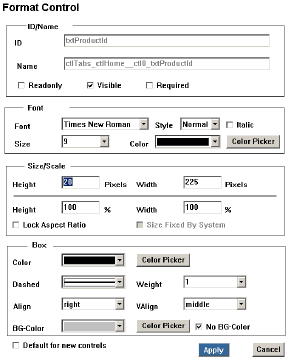
1 Right-click a field, then select Properties from the shortcut menu.The Format Control window opens (Figure 72).
2 The ID and Name fields are locked. See “Setting Label Properties” on page 88 to change the Label properties.
3 Select a visibility option from the ID/Name section:
• Read only - the field will be visible, but locked.
• Visible - the field will be visible and editable (if not read-only) for users with edit access to the form section.
• Required - the field will be visible and editable for users with edit access to the form section, as well as flagged as a required field. Users will receive an error message when attempting to save a page with a blank required field.
Note
Currently both standard and user fields can be flagged as Required in their properties, however, the feature takes affect only on user fields.
4 From the Font section, select a Font type from the list.
5 Select the font Style from the list.
6 Click the Italic check box if needed.
7 Select the desired font Size from the list.
8 Select a predefined color from the Color list or click Color Picker to select a custom color.
9 Select a Fill Color from the list or click Color Picker to select a custom color.
10 From the Size/Scale section, enter the shape Height and Width in the fields.
or
Type the Height%and Width % in the Size/Scale fields
Note
Lock Aspect Ratio is enabled by default. If you wish to scale just the height or width, de-select the check-box prior to changing the Size/Scale.
11 From the Box section, select the Color from the list or click Color Picker to select a custom color.
12 Select a style for the line from the Dashed list.
13 Select the line Weight from the list.
14 Select the text alignment from the Align list.
15 Select the vertical text alignment from the VAlign list.
16 Select a background color from the BG-Color list or click Color Picker to select a custom color.
or
Click the No BG-Color check box if you wish to make the field transparent.
Caution
If a background color is selected and this field is still checked, the color will not appear on the form.
17 Apply the selected preferences to all new fields by selecting the Default for new controls check box. This will affect any fields added to the form from both control lists.
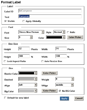
Figure83 The Format Label window
18 Click Apply to save and close. The selected format is applied to the field.
1 Right-click the label field and select Properties from the shortcut menu to open the Format Label window (Figure 73).
2 The Label ID field is locked and read only.
3 Type the label text that will appear on the form in the Text field.
4 Select a visibility/change option:
• Visible - the label will be visible for users with view access to the section.
• Apply Globally - the label field name will be changed on every form where it appears and where the apply globally has been selected for that label.
5 From the Font section, select a Font type from the list.
6 Select the font Style from the list.
7 Click the Italic check box if needed.
8 Select the desired font Size from the list.
9 Select a predefined color from the Color list or click Color Picker to select a custom color.
10 From the Size/Scale section, enter the shape Height and Width in the fields.
or
Type the Height %and Width % in the Size/Scale fields.
Note
Lock Aspect Ratio is enabled by default. If you wish to scale just the height or width, de-select the check-box prior to changing the Size/Scale.
Tip
You may alternatively select the Auto Resize Box option if you wish the label text box to automatically adjust to the entered text.
11 From the Box section, select the Border-Color from the list or click Color Picker to select a custom color.
12 Select a style for the line from the Dashed list.
13 Select the line Weight from the list.
14 Select the text alignment from the Align list.
15 Select the vertical text alignment from the VAlign list.
16 Select a background color from the BG-Color list or click Color Picker to select a custom color.
or
Click the No BG-Color check box if you wish to make the label background transparent.
Caution
If a background color is selected and this box is still checked, the color will not appear on the form.
17 Apply the selected preferences to all new labels by selecting the Default for new controls check box. This will affect any labels added to the form from both control lists.
18 Click Apply to save and close. The selected format is applied to the label.
1 From the Form Design window, click the object you wish to resize. Black handles appear around the object.
2 Drag the handles to resize the field.
Tip
To keep an object proportional while resizing, hold the Ctrl key down while dragging one of the corner handles. This is helpful for images and logos.
3 You may also make objects the same size by selecting the objects, right-clicking on one of the selected objects and selecting an option from the short cut menu:
Make the same size>
• Both
• Width
• Height
Tip
To select multiple objects either click a blank part of the form and drag over a range of fields or press [Shift] and click on each field. Using either method, the first field or label the cursor touches is used as the base for the change.
Figure84 The Align Controls window
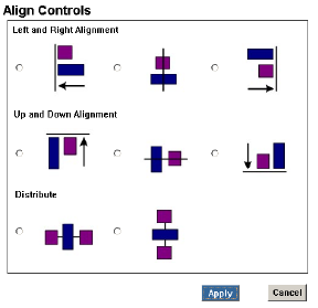
1 From the Form Design window, click to select the desired fields, then right-click and select Align Controls from the shortcut menu. The Align Shapes window opens (Figure 74).
Tip
To select multiple objects either click a blank part of the form and drag over a range of fields or press [Shift] and click on each field. Using either method, the first field or label the cursor touches is used as the base for the change.
2 Select the alignment and/or distribution that you would like to apply.
3 Click Apply to save and close. The shapes are aligned and distributed as selected.
Advanced Positioning of Objects
1 From the Form Design window, click to select the desired fields, then right-click and select Advanced Positioning from the shortcut menu. The Advanced Positioning window opens (Figure 75).
Figure85 The Advanced Positioning window
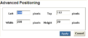
2 Enter the position of the object from the Left in pixels.
3 Enter the position of the object from the Top in pixels.
4 Enter the Width of the object in pixels.
5 Enter the Height of the object in pixels.
6 Click Apply. The object is resized and positioned as selected.
1 From the Form Design window, click to select the objects you wish to nudge.
Tip
You may click and drag around items or hold the Shift key while clicking to select multiple items.
2 Right-click and select the direction in which you wish to nudge (Up/Down/Left/Right) from the shortcut menu. The objects are nudged in the appropriate direction.
Note
Objects are nudged to the Form Designer gridlines.
Figure86 The Staircasing window
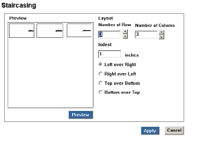
1 From the Form Design window, select the objects to staircase, then right-click and select Staircasing from the shortcut menu. The Staircasing window opens (Figure 76).
Tip
You may click and drag around items or hold the Shift key while clicking to select multiple items.
2 Select the number of “steps” by using the arrows to determine the number of Rows and Columns.
3 Type the number of Inches by which each object should be indented in the Indent field.
4 Define the layout of the selected objects by selecting either the Left over Right, Right over Left, Top over Bottom, or Bottom over Top radio button. The selected option will end up being on the top-most layer of the staircase.
5 Click Preview to view the selected options or click Apply to save and close. The selected objects are redistributed in a staircased layout.
Moving a Field to a Different Section
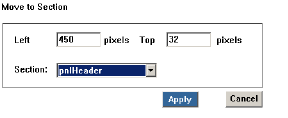
The Move to Section window
1 From the Form Design window, right-click and select Move to Section from the shortcut menu. The Move to Section window opens (Figure 77).
2 Type the field position from the Left and Top of the section.
3 Select a Section from the list.
Note
The field will use the security of the section to where it is moved. The section will not be changed in Data Dictionary.
4 Click Apply. The field is moved to the selected section.
From the Form Design window, right-click the field(s) you wish to delete, then select Delete from the shortcut menu.
Caution
You may only delete User Fields from the form.
Some forms have configurable tables. In Product Manager, the Simplified and 3D BOMs have configurable tables. In Source, the Cost Details, Cost Scenario Summary, Compared Costing Variation Summary and Cost Scenario Comparison forms have configurable tables.
1 From the form list, select a Simplified or 3D BOM form. The General Information pages appears for the form.
2 Click the Configurable Table tab. The Manage Configurable Table page opens (Figure 76).
Figure88 The BOM Manage Configurable Table page
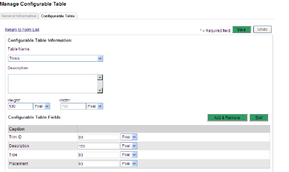
3 Select a Table Name from the list. The table information appears.
4 Type a Description in the field.
5 Type a Height for the table. The Width is locked.
Note
If the height of the list of items exceeds the table height set here, the table will get a vertical scrollbar on the form.
Figure89 The Add Field window
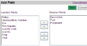
6 Add or remove fields for the selected table:
a Click the Action>Fields>Add & Remove. The Add Field window opens (Figure 77).
Tip
You may alternatively click the Add & Remove button.
b Select the desired field(s) from the Available Fields list, then click > to move it to the Selected Fields list.
c Click Save. The page is refreshed and the selected fields appear.
d For each field, type the field size in pixels.
Note
If the total width of all the columns exceeds the table width, the table will get a horizontal scrollbar on the form.
Figure90

The Set Sort Order window
7 You may also sort the table fields:
a Click Action>Fields>Sort. The Set Sort Order window opens (Figure 78).
Tip
You may alternatively click the Sort button.
b Select a field from the list and use the arrows to move it up or down the list.
c Click Apply and Close Window. The Configurable Table Fields are sorted as defined.
8 Click Save.
9 Repeat for all tables available in the Table Name list.
Configuring Source Costing Form Tables
1 From the form list, select a Cost Details, Cost Scenario Summary, Compared Costing Variation Summary or Cost Scenario Comparison form. The General Information pages appears for the form.
2 Click the Configurable Table tab. The Manage Configurable Table page opens (Figure 81).
Figure91 The Source Forms Manage Configurable Table page
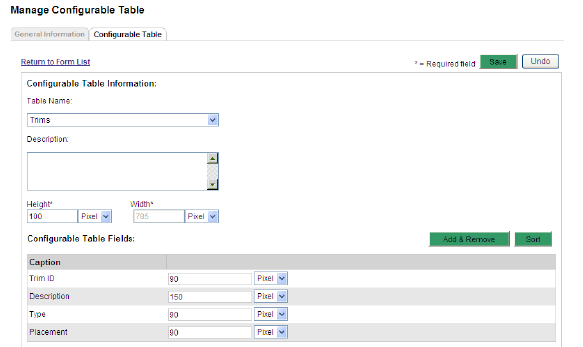
3 Type a Description in the field.
4 Add or remove fields for the selected table:
Figure92 The Source Costing Forms Add Field window
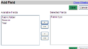
a Click the Action>Fields>Add & Remove. The Add Field window opens (Figure 82).
Tip
You may alternatively click the Add & Remove button.
b Select the desired field(s) from the Available Fields list, then click > to move it to the Selected Fields list.
c Click Save. The page is refreshed and the selected fields appear.
d For each field, type the field size in pixels.
Figure93

The Set Sort Order window
5 You may also sort the table fields:
a Click Action>Fields>Sort. The Set Sort Order window opens (Figure 78).
Tip
You may alternatively click the Sort button.
b Select a field from the list and use the arrows to move it up or down the list.
c Click Apply and Close Window. The Configurable Table Fields are sorted as defined.
6 Select a Caption name and rename it.
Caution
When you rename a Caption in one form variation it will change in all form variations of all Source Costing forms using it.
7 Repeat for each Caption you wish to rename.
8 Click Save.
The Costing Scenario Summary form variation in Source has an additional tab that enables an administrator to configure the calculations used to cost products.
The standard field formulas are available on this tab and can be modified. User fields can be added and formulas defined for them.
Fields can be designated as data input or calculated result fields. Any data input or sql user fields that need to be referenced in a calculation and those that will calculate results must be added to the form on this tab.
1 From the General Information page of a Costing Scenario Summary, click the Calculated Fields tab. The Manage Forms page opens (Figure 84).
Figure94 The Source Manage Forms Calculated Fields page
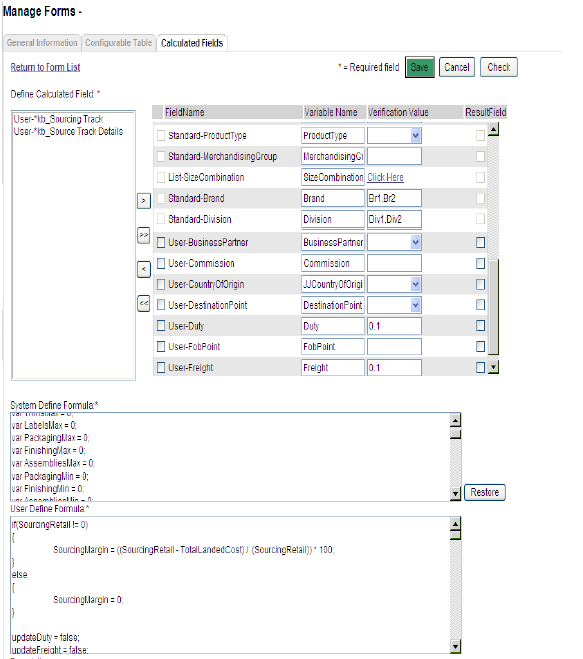
2 Select the user fields from the Define Calculated Field list that should be configured as either cost data input or calculated results, and click > to move them to the Field Name list.
3 Scroll to the bottom of the Field Name list and click the ResultField check-box for each of the user fields you added that will need formulas.
4 Type java format formulas in the User Define Formula field for each new result field added to the form. Use the Variable Name from the table above as the field reference for any field used in the formula.
5 Modify standard field formulas in the System Defined Formula field.
Tip
The default system-defined formulas may be brought back by clicking the Restore button.
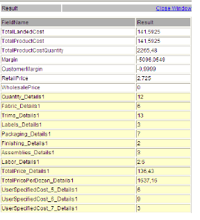
6 Click Check to verify your field values and calculations. The Results window opens and displays the formula results using the entered Verification Value for each field.
Caution
You will be prompted with an error message if your calculations and formulas are incorrect. Verify your formulas and click Check again.
7 Click Save.
1 From the Form list, select the forms you wish to copy.
2 Click Action>Copy. A confirmation message appears.
3 Click OK. The form is copied and added to the Configurable Forms list prefixed with “Copy of”.
1 From the Form list, select the forms you wish to delete.
Caution
Standard Forms may not be deleted. Only form variations can be deleted.
2 Click Actions>Delete. A confirmation message appears.
3 Click OK. The form is deleted.
Warning
This action may not be undone and the form will be permanently deleted.
Note
Only form variations that have not been used on any items can be deleted.
Create Form Sets and set up which forms will be automatically added to a product when users create new products.
Viewing and Editing a Form Set
1 From the Business Process Management tab, click the Form Sets link in the Configuration section. The Form Sets list for all Modules appear.

2 Select a Module from the list. The Form Sets for the module appear.
3 Click the link of any form set in the list. The Form Set Details window opens.
4 Modify the information, then click Save.
Caution
See “Filtering Rules” on page 19 for important information on filters before removing Division filters.
1 Click the column header to sort the list in ascending/descending order by the selected column.
2 Click a different column header to sort by a different column in ascending order.
1 From the Form Set list page, select a Module from the list. All Form Sets for the module are listed.
2 Select the Form Set you wish to copy, then click Action>Copy. A confirmation message appears.
3 Click OK. The page is refreshed and the Form Set is copied. It is listed as “Copy of...”.
Figure97 The New Form Set window
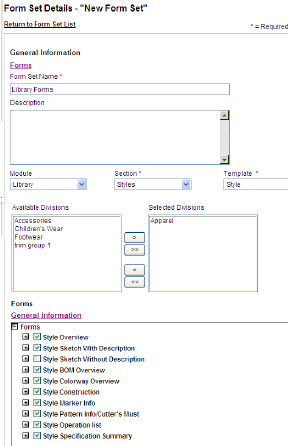
1 From the Form Set list, click Actions>New. The New Form Set window opens.
2 Type a Form Set Name in the field. This field is required.
3 Enter a Description.
4 Select the Module from the list.
5 Select the Section from the list. This field is required.
6 For Library Styles Form Set, you may also select a Style or Assembly Template from the list.
7 Select the Form Type from the list.
8 Select a Division from the Available Divisions list that should have access to the form set, then click > to move them to the Selected Divisions list.
Caution
See “Filtering Rules” on page 17 for important information on filters before removing Division filters.
Note
The Form Set will only be available to be added in Item Types with same Division filtering and available for products in folder with the save Division filtering. Any form that is not filtered will be available for all divisions.
9 Click the + to open all existing variations of a Standard form.
10 Select Forms from the list.
Caution
You may only select either the Standard form or a variation of that form, but never both.
11 Click Save.
1 From the Form Set list page, select a Module from the list. All Form Sets for the module are listed.
2 Select the Form Set(s) you wish to delete, then click Action>Delete. A confirmation message appears.
3 Click OK. The Form Set is deleted.
Warning
This action may not be undone and the Form Set will be permanently deleted.
Create Item Types, add basic metadata, and associate Form Sets to them to speed up the product creation process.
Product Manager and Line Opimizer Product Item Types can contain form sets for both modules because a product can be created in one of the modules and shared with the other later. When the product is shared, the form set for the destination’s module defined on the source module’s Item Type will be added to the product. Item Types for Fabric & Trim do not have this extra form set assignment.
There may also be template information associated to the Item Type which would also automatically be copied or linked to your fabric, such as an item type named knit interlock may have a construction template for interlock fabric attached to it.
Viewing and Editing an Item Type
1 From the Business Process Management tab, click the Item Types link in the Configuration section. The Item Types window opens.
Figure98 The Item Types window

2 Select a Module from the list. The list of Item Types is filtered.
3 Click the link of any Item Type in the list. The Item Type Details window opens.
4 Modify the information, then click Save.
Caution
See “Filtering Rules” on page 19 for important information on filters before removing Division filters.
1 Click the column header to sort the list in ascending order by the selected column.
2 Click the same header again to sort the list in descending order.
3 Click a different column header to sort by a different column in ascending order.
Figure99 The New Item Type window

1 From the Item Type list, click Actions>New. The New Item Type window opens.
2 Type a Item Type Name in the field. This field is required.
3 Enter a Description.
4 Select a Module from the list. This is required and defaults to the module selected in the Item Type list dropdown filter.
5 Select a Section from the list. This is required.
6 Click Save. The Item Type Details window appears.
7 Select a Division from the Available Divisions list that should have access to the form set, then click > to move them to the Selected Divisions list.
Caution
See “Filtering Rules” on page 19 for important information on filters before removing Division filters.
8 Add Metadata information for this Item Type. See “Adding Metadata to an Item Type” below.
9 Select Forms Sets for this Item Type. See “Adding Form Sets to an Item Type” on page 104 for details.
10 Add Any Templates you wish to associate with this Item Type. “Adding Template Information to an Item Type” on page 105.
11 Add Attachments. See “Adding Attachments to an Item Type” on page 105 for details.
12 Click Save.
Adding Metadata to an Item Type
Figure100 The Item Type Metadata
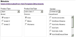
1 From the Metadata section of the Item Type page (Figure 90), select a Product Type from the list. The Product SubType list is filtered.
Note
This example is for a Product Manager Product Item Type. Metadata fields available are dependent on the Module and Section selected.
2 Select a Product SubType from the list.
3 Select a Gender from the list.
4 Select a Brand check box. The associated Divisions appear.
5 Select a Divisions check box. The associated Departments appear.
6 Select a Department check box.
Note
Metadata drop-down values are filtered by the Divisions associated to the Item Type for Product Manager and Line Optimizer Item Types.
Adding Form Sets to an Item Type
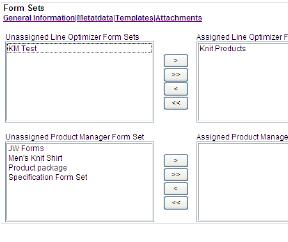
section
1 From the Form Sets section of the Item Type page (Figure 91), select a Form Set from the Unassigned Line Optimizer Form Sets list, then click > to move it to the Assigned Line Optimizer Form Sets list.
Note
Available Form Sets are filtered by the Divisions associated to the Item Type.
2 Select a Form Set from the Unassigned Product Manager Form Sets list, then click > to move it to the Assigned Product Manager Form Sets list.
Note
This extra Form Set assignment field is not on Item Types for Fabric & Trim.
3 Repeat for additional form sets if needed.
Tip
Click < to remove selected Form Sets from the Assigned Form Sets list or click << to remove all Assigned Form Sets from the list.
Adding Template Information to an Item Type
Figure102 The Select Template for Item Type

1 Click the Library icon to open the Select from Library Structure window.
2 Select a template folder. The Select Template for Item Type page appears (Figure 92) with all templates that can be associated to the item type.
3 Select one or more templates, then click Select. The confirmation message appears.
4 You may click the Return to Structure link add templates from another folder.
5 Click Close Window when all necessary templates have been added. The window closes and the Item Type details page refreshes to show the templates added to the Templates section.
Adding Attachments to an Item Type
1 Click the Update Attachment link to open the Attachment List window.
2 Click Browse to navigate to your folder and select the desired file.
3 Click Open. The file path appears in the Browse field.
4 Click Attach. The file appears in the Attachments list.
5 Repeat steps 2 and 4 for all desired files.
6 Click Save.
7 Click the Close Window link to exit the Attachment List window. The page is refreshed with the added file(s) in the Attachments section.
From the Attachment section of the Item Type, click the attachment name. The attachment opens in a new window.
Caution
You may be prompted with a save attachment message when trying to view the attachment.
1 From the Update Attachments window, click the Perform Action check-box for the file you wish to download.
2 Click the Download button. The File Download window opens.
3 Click the Save button. The Save As window opens.
4 Select the folder where you wish to save this attachment, then click Save. The attachment is saved to the selected location.
1 Click the Update Attachment link to open the Attachment List window.
2 Click the Perform Action check box of the files you wish to remove.
3 Click Delete. The page is refreshed without the selected file(s) in the Attachment section.
Print Templates allow you to set up print information. When printing, you may want information to be printed differently than it appears on screen. You may also select to print different information depending on access rights, forms, applications, etc.
By creating Print Templates, you can define print formats and layout for the whole company or for selected divisions.
The grid and the Snap to Grid feature are both enabled on the Print Template Designer by default. Because web print template fields must be aligned in a grid and cannot be overlapped, it is beneficial to keep both of these features enabled, however sometimes it is necessary to disable one or both.
Viewing the Print Template List
From the Business Process Management tab click the Print Templates link in the Configuration section. The Print Templates page opens.
Figure103
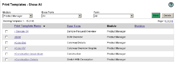
The Print Templates page
Sorting the Print Template List
1 From the Print Templates page, select a Module from the list. The page refreshes to list only the print templates for the selected application.
2 To further refine your sort, select a Base Form from the list.
3 Select a Form from the list. All Print Templates for the selected criteria are listed.
Tip
You may click a column header (Base Form, Division) to sort the list ascending or descending order.
Viewing/Editing Print Template Details
1 From the Print Templates list, click a Print Template Name. The Print Template Details page opens.
2 Modify the template information as needed.
3 Click Save.
1 From the Print Templates page, click Actions>New. The Print Template Details page opens.
Figure104 The Print Template Details page

2 Type a Print Template Name in the field. This field is required.
3 Enter a Description in the field.
4 Select a Paper Size from the list. This field is required.
5 Select a Layout from the list. This field is required.
6 Select a Base Form from the list. This field is required.
7 Select a Form from the list. This field is required.
8 Select a Division from the Available Divisions list and click > to move it to the Selected Divisions. Only selected Divisions will have access to this Print Template.
Note
If the form that the template is based on is filtered by division, the same division as the form will be automatically selected and the other divisions will not appear in the available list.
9 Select a Logo Selection from the list. Logos associated with divisions will become available once those divisions have been filtered. The logo is printed on the right of the page header.
10 Select a Copyright Selection from this list. This information will appear at the bottom of each printed page.
11 Click Save. The page is refreshed and the Print Designer button becomes available.
12 Use the Print Template Designer to setup the page information and layout. See “Designing a Print Template” below for details.
13 Click Save. The Print Template appears in the list of Print Templates.
1 From the Print Template Details page, click the Print Designer button. The Print Template Designer page opens.
Caution
The Print Designer button is only available after you have clicked the Save button when creating a new print template.
Figure105 The Print Template Designer page
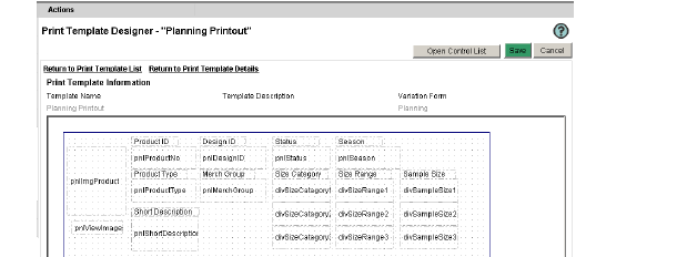
2 Add fields. See “Adding Controls” on page 111.
3 Define the field properties. See “Defining Field Properties” on page 112.
4 Modify the field. See “Modifying Fields” on page 113.
Tip
You can select a field and use the handles to resize it. Or click and drag it to a different location, however you cannot overlap fields.
5 Modify the section. See “Modifying Sections” on page 114.
6 Click Save.
Using Print Template Gridlines
1 Right-click on the form and select Snap to Grid to disable this feature.
2 Repeat step 1 to re-enable the Snap to Grid feature.
3 Right-click on the form and select Hide Gridlines. The gridlines will disappear and Snap to Grid is disabled.
4 Right-click on the form and select Show Grid from the shortcut menu. The gridlines appear. The Snap to Grid feature will be enabled by default and helps align fields to the grid while dragging them.
Selecting a Section Background Color
Figure106 The Background Color window

1 From the Print Template Designer window, right-click a blank space on a section and select Background Color from the shortcut menu. The Background Color window appears (Figure 96).
2 Select a predefined color from the Color list or click Color Picker to select a custom color.
3 Click Apply. The section background color changes.
Figure107 The Show/Hide Sections window

1 From the Print Template Designer window, right-click a blank space on a section and select Show/Hide Sections from the shortcut menu. The Show/Hide Sections window appears (Figure 97).
2 Select the Show check box of the section(s) you wish to render visible. Uncheck a section to hide it.
Caution
You may only hide sections that do not contain required fields. Sections that cannot be hidden are listed as True in the Required column.
3 Click Apply. The section is shown/hidden.
Figure108 The Select Control window
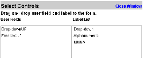
1 From the Print Template Designer page, click the Open Control List button. The Select Control window opens.
2 Click and drag a User Field onto the form.
3 Click and drag a Label List onto the form.
4 Click the Close Window link to return to the Template Designer.
5 Click the Open Standard Control List button. The Select Controls window opens and shows any standard fields and labels that have previously been hidden on the print template and any new standard fields that were added to the print template in an upgraded version.
6 Click and drag Standard Fields onto the print template in the appropriate section.
7 Click and drag the label from the Label List onto the print template next to or above the Standard Field.
8 Click Save. The print template is modified.
Figure109 The Format Control window

1 From the Print Template Designer page, right-click a field, then select Properties from the shortcut menu. The Format Control window opens.
2 The ID and Name fields are read-only and may not be edited.
3 Select a view option:
• Read-only - the field is locked.
• Visible - the field is not hidden.
• Apply Globally - field properties will be changed on every form where it appears.
• Required - the field is flagged as required.
4 From the Font section:
a Select a Font type from the list.
a Select a font Style from the list.
b Click the Italic box to italicize the text.
c Select a Size from the list.
d Select a Color.
or
Use the Color Picker to choose a color. See “Using the Color Picker” on page 115.
5 From the Size/Scale section:
a Type a Height and Width in Pixels in the fields.
or
Type a Height and Width in Percentage in the fields.
b Click the Lock Aspect ration to enlarge/reduce the field size proportionally.
c If the Size Fixed By System check box is selected, the field’s size cannot be modified.
6 From the Box section:
a Select a Border Color from the list.
or
Use the Color Picker to choose a color. See “Using the Color Picker” on page 115.
b Select a line type from the Dashed list.
c Select a line Weight.
d Select a horizontal alignment for the text from the Align list.
e Select a vertical alignment for the text from the VAlign list.
f Select a background color for the text box from the BG Color list.
or
Use the Color Picker to choose a color. See “Using the Color Picker” on page 115.
g You may also click the No BG Color to make the field transparent.
7 Click the Default for new label check box to apply these field properties to new fields.
8 Click Apply. The window closes and the field properties are applied to the selected control.
9 Click Save.
1 From the Print Template Designer page, right-click a field to open the shortcut menu.
Note
The Print Template Designer uses the same functions as the Form Designer. Please see “Using the Form Designer” on page 84 for detailed steps.
2 Select one of the following options:
• Delete - remove the field to the Control list?
• Properties - see “Defining Field Properties” above.
• Align Controls - available for multiple selected fields. Offers the options to align fields Left/Right, Up/Down, and Distribute evenly.
• Make the Same Size - will apply same Width/Height or Both to selected fields.
Note
When aligning or making controls the same size, the properties of the first selected control will be applied to the others.
• Staircasing - available for multiple selected fields.
• Advanced Positioning - available for single selected fields. Enter the Width and Height of field and spacing from Top and Left of the form.
• Nudge Up/Down/Left/Right - snaps to grid
• Move to Section - opens a list of sections available in which to move the field(s).
3 Click Save.
1 From the Print Template Designer page, right-click a blank space of a section to open the shortcut menu.
Note
The Print Template Designer uses the same functions as the Form Designer. Please see “Using the Form Designer” on page 84 for detailed steps.
2 Select one of the following options:
• New Block - ensures that fields will be printed together. Click and drag the green handle over the fields you wish to group.
• Undo/Redo - allows an action to be undone or redone.
• Cut/Copy/Paste/Delete - use these functions after selecting fields in a section.
• Select All - selects all fields in a section.
• Hide Grid - hide the section gridlines.
• Snap to Grid - fields will align themselves with gridlines when nudging or aligning.
• Background Color - choose a color or use the Color Picker to define the section color. See “Using the Color Picker” on page 115.
• Show/Hide Section - opens a dialog box with all sections listed. Sections with a check mark are visible.
• Section Property - see “Defining Section Properties” below.
3 Click Save.
Figure110 The Section Property window
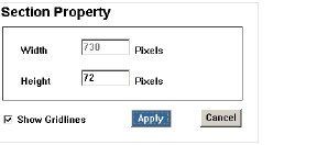
1 From the Print Template Designer page, right-click a field, then select Section Property from the shortcut menu. The Section Property window opens.
Note
The Print Template Designer uses the same functions as the Form Designer. Please see “Using the Form Designer” on page 84 for detailed steps.
2 Enter the section Width in Pixels.
3 Enter the section Height in Pixels.
4 Click the Show Gridlines check box.
5 Click Apply to close the window.
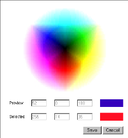
The Color Picker window
1 Click the Color Picker link to select a color visually. The Color Picker window opens (Figure 101).
2 Select a color. The associated color information appears in the Preview fields.
3 Click Save. The window closes.
1 From the Print Templates list, click a Print Template Name. The Print Template Details page opens.
2 Modify the template information. “Creating Print Templates” on page 108.
3 Use the Print Template Designer to modify the page information and layout. See “Designing a Print Template” on page 109.
4 Click Save.
1 From the Print Templates list, select the check box(es) of the template(s) you wish to copy.
2 Click Actions>Copy. The confirmation message appears.
3 Click OK. The template is copied and listed as “Copy of...”.
1 From the Print Templates list, select the check box(es) of the template(s) you wish to delete.
2 Click Actions>Delete. A confirmation message appears.
3 Click OK. The template is removed from the page and from all Print Sets.
Warning
This will remove the Print Template from all Print Sets in which it is currently defined. this action may not be undone.
The Print Sets section allows you to group your Print Templates. You can select which forms to print as well as define access rights per division ensuring that your teams can execute standardized print jobs quickly and efficiently.
From the Business Process Management tab click the Print Sets link in the Configuration section. The Print Sets page opens.
Figure112
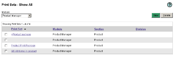
The Print Sets page
From the Print Sets page, select a Module from the list. The page refreshes to list only the print sets for the selected application.
Tip
You may click a column header (Print Set, Section, Division) to sort the list ascending or descending order.
Viewing/Editing Print Set Details
1 From the Print Sets list, click a Print Set name. The Print Set Details page opens.
2 Modify the print set information as needed.
3 Click Save.
1 From the Print Sets page, click Actions>New. The Print Set Details page opens.
Figure113 The Print Set Details page
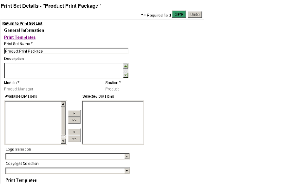
2 Type a Print Set Name in the field. This field is required.
3 Enter a Description in the field.
4 Select a Division from the Available Divisions list and click > to move it to the Selected Divisions. The Division selected filters the list of print templates available. Only selected Divisions will have access to this Print Set.
5 Select a Logo Selection from the list. Logos associated with divisions will become available once those divisions have been filtered. The logo is printed on the right of the page header.
6 Select a Copyright Selection from this list. This information will appear at the bottom of each printed page.
Note
The Logo and Copyright selection made on the Print Set will overwrite and selection made on the included Print Templates.
7 Add Print Template information. See “Adding Print Templates to Print Sets” on page 118.
8 Click Save. The Print Set appears in the list of Print Sets.
Adding Print Templates to Print Sets
1 From the Print Sets Details page, select a Paper Size from the list. This filters the list of available print templates to those matching this format. This field is required.
2 Select a Layout from the list. This filters the list of available print templates to those matching this format. This field is required.
3 Select the check box of the Print Templates you wish to include in the Print Set.
4 Click Save.
1 From the Print Sets list, select the check box(es) of the set(s) you wish to copy.
2 Click Actions>Copy. The confirmation message appears.
3 Click OK. The set is copied and listed as “Copy of...”.
1 From the Print Sets list, select the check box(es) of the set(s) you wish to delete.
2 Click Actions>Delete. A confirmation message appears.
3 Click OK. The set is removed from the page and from all Print Sets.
Warning
This action may not be undone and the print set will be permanently deleted.
Workflow administrative tasks are part of Fashion PLM and are linked to the administration of other modules such as Product Manager. User creation and business partner creation, as well as folder structure, are executed in the same screens used for all the other Fashion PLM modules.
Since Workflow requires a specific configuration, a configuration section is available for it.
Workflow user groups are used to assign and manage groups of users. Create and maintain user groups including access rights in this section.
Users can belong to more than one group. In these cases, the most permissive access rights will prevail. For example, a user with delete access in one group and read only access in another will automatically have delete access.
1 From the Business Process Management tab click User Groups. The User Groups page displays.
2 Select a group from the Group drop-down list.
3 Select a company from the Company drop-down list. The following display:
• The full pool of available users displays in the Available Users box.
• Members of the selected group and the selected company display in the <Group Name> Members box.
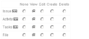
• Group access rights for issues, activities, tasks, and files display on the right side of the page (Figure 104).
Tip
Group access rights are assigned from least access rights (None), to most access rights (Delete).
Note
There is no access right section for the Administrator group since they have unrestricted access.
1 From the User Groups page, click Add Group.
2 Enter a group name in the Group field.
3 Click OK. The User Groups page displays with the new group name in the Group field. The new group name is added to the Group drop-down list.
4 Select a company. The full pool of available users displays in the Available Users box.
5 In the Available Users box, select one or more users to add to the group.
6 Repeat steps 4 and 5 as needed to add users from other companies to the group.
Tip
To select a list of items, hold the shift key while selecting the first and last item in the list. To select several separate items, hold the control key while selecting them.
7 Click Add. The users are moved to the <New Group Name> Members box.
8 Assign access rights to the group for issues, activities, tasks, and files as follows:
• None — No access rights are allowed.
• View — The Workflow user group can view.
• Edit — The Workflow user group can edit.
• Create — The Workflow user group can create.
• Delete — The Workflow user group can delete.
Tip
Group access rights are assigned from least access rights (None), to most access rights (Delete).
9 Click Save.
1 From the User Groups page, select a group from the Group drop-down list.
2 Select a company from the Company drop-down list. The following display:
• The full pool of available users displays in the Available Users box.
• Members of the selected group and the selected company display in the <Group Name> Members box.
• Group access rights for issues, activities, tasks, and files display on the right side of the page (Figure 104).
Tip
Group access rights are assigned from least access rights (None), to most access rights (Delete).
3 Select the user you want to edit and click one of the following buttons:
• Add > — Adds a user to the group Members box.
• < Remove — Removes a user from the group Members box.
• Move Up — Moves a user up in the group Members box.
• Move Down — Moves a member down in the group Members box.
Alternately, click one of the following buttons:
• Add All >> — Adds all the available users to the group Members box.
• << Remove All — Removes all the users from the group Members box.
4 Click Save.
1 Select a group from the Group drop-down list.
2 Select a company from the Company drop-down list. The following display:
• The full pool of available users displays in the Available Users box.
• Members of the selected group and the selected company display in the group Members box.
• Group access rights for issues, activities, tasks, and files display on the right side of the page (Figure 104).
Tip
Group access rights are assigned from least access rights (None), to most access rights (Delete).
3 Click Remove Group. A confirmation dialog box displays.
4 Click OK.
Workflow labels enables you to assign your company’s current names and descriptions to screens, tabs, and field names. This customization provides you with flexibility and helps users work within a familiar environment. Create and maintain labels in this section.
1 From the Business Process Management tab, click Labels. The Labels page displays.
2 Select a screen from the Choose Screen drop-down list.
a If you want to rename the screen, type the new name in the = field.
b Click Rename.
3 Select a tab from the Choose Tab drop-down list.
a If you want to rename the tab, type the new name in the = field.
b Click Rename.
4 Select a label from the Choose Label drop-down list.
a If you want to rename the label, type the new name in the = field.
b Click Rename.
The results of your changes display in the Affects section of the page. These changes occur immediately in Workflow.
UseWorkflow lookups to create drop-down list elements for fields in Workflow forms. For example, add Holiday to the Season drop-down list.
1 From the Business Process Management tab click Lookups. The Lookups page displays.
2 Select a screen from the Select Screen drop-down list.
3 Select a tab from the Select Tab drop-down list.
4 Select a table from the Select Table drop-down list.
5 Add one or more items as follows:
a Enter the name of the item in the Item field.
b Press Enter or click Add >>.
Tip
To save each change as you make it, select Save on Change?.
The results of your changes display in the Affects section of the page. These changes occur immediately in Workflow.
1 From the Lookups page, select a screen from the Select Screen drop-down list.
2 Select a tab from the Select Tab drop-down list.
3 Select a table from the Select Table drop-down list.
4 Select the item you want to edit and click one of the following buttons:
• << Remove — Removes the item.
• Move Up — Moves the item up.
• Move Down — Moves the item down.
• Rename — Renames the item.
Tip
To save each change as you make it, select Save on Change?.
The results of your changes display in the Affects section of the page. These changes occur immediately in Workflow.
Workflow issue lookups allow you to define types of issues.
1 From the Business Process Management tab click Issue Lookups. The Issue Lookups page displays.
2 Select a tab as follows:
• The Lookups tab contains custom issue lookups.
• The Others tab contains system pre-set issue lookups.
3 From the tab you have selected, select an item. The issue lookup displays.
1 From the Issue Lookups page, select either the Lookups tab or the Others tab.
2 On the tab you have selected, select an item.
3 Add one or more sub-items as follows:
a Enter the name of the sub-item.
b Press Enter or click Add >>.
4 Click Save.
1 From the Issue Lookups page, select either the Lookups tab or the Others tab.
2 On the tab you have selected, select an item.
3 Select the sub-item you want to edit and click one of the following buttons:
• << Remove — Removes the sub-item.
• Move Up — Moves the sub-item up.
• Move Down — Moves the sub-item down.
• Rename — Renames the sub-item.
Alternately, click the following button:
• Remove All — Removes all the sub-items.
4 Click Save.
Workflow folders allow you to customize folder names for activities, issues, and tasks.
1 From the Business Process Management tab click Folders. The Folders page displays.
2 Select Activity, Issue or Task from the drop-down list. The folder list for that section displays.
1 From the Folders page, select Activity, Issue or Task from the drop-down list.
2 Click Add Folder. A new folder displays.
3 In the New Folder field, name the new folder.
4 Press Enter or click Add.
1 From the Folders page, select Activity, Issue or Task from the drop-down list.
2 Select the folder you want to delete.
3 Click Delete. A confirmation dialog box displays.
4 Press OK.
Workflow Workflow (Issue Rules) sets up the notification rules for issues. Make these rules as simple or as complex as you need to make them.
Since creating rules for your issues can become very complicated, it is recommended that you initially create simple rules. You can add more rules, refining your process, at any time.
Viewing Workflow (Issue Rules)
1 From the Business Process Management tab click Workflow. The Workflow page displays.
2 Select any of the Workflow (Issue Rules) tabs, as follows:
• Reports — Provides a list of the issue reporting rules.
• Acknowledge — Provides a list of the issue acknowledgement rules.
• Hold — Provides a list of the issue hold rules.
• Resume — Provides a list of the issue resume rules.
• Action — Provides a list of the issue action rules.
• Close — Provides a list of the issue close rules.
• Reopen — Provides a list of the issue reopen rules.
• Archive — Provides a list of the issue archive rules.
Creating a Workflow (Issue Rules)
1 From the Business Process Management tab click Workflow. The Workflow (Issue Rules) page displays.
2 Select the tab you want to create an issue rule on. The list for that tab displays with the following fields:
• ID — The ID number for the rule.
• Party — The parties associated with the rule.
• Issue Type — The issue type.
• Deliverables — The deliverables.
• Locations — The locations.
• Other — The other items associated with that rule.
• E-mail — The email recipients for the rule.
• Next Stage — The stage to follow the rule.
3 Click Add. The new workflow (issue rule) displays
4 Click the selection icon in each field to refine the rule.
Caution
The default setting for new rules is Any. If no email address is added, the rule will not be applied.
5 Click Save.
Editing a Workflow (Issue Rules)
1 From the Business Process Management tab click Workflow. The Workflow (Issue Rules) page displays.
2 Select the workflow (issue rule) you want to edit.
3 Click the edit icon. The expanded rule displays for editing.
4 Edit the rule.
5 Click Save.
Deleting a Workflow (Issue Rules)
1 From the Business Process Management tab click Workflow. The Workflow (Issue Rules) page displays.
2 Select the workflow (issue rule) you want to delete.
3 Click Delete.
Workflow quick search allows you to search issues, activities, and tasks. In addition, you can set one default search each for issues, activities, and tasks.
1 From the Business Process Management tab click Quick Search. The Quick Search page displays.
2 Select Issue, Activity, or Task from the drop-down list.
3 In the Available box, select the items you want to search on and click one of the following buttons:
• Add > — Adds an item to the Selected box.
• < Remove — Removes an item from the Selected box.
• Move Up — Moves an item up in the Selected box.
• Move Down — Moves an item down in the Selected box.
Tip
To select a list of items, hold the shift key while selecting the first and last item in the list. To select several separate items, hold the control key while selecting them.
Alternately, click one of the following buttons:
• Add All >> — Adds all the available items to the Selected box.
• << Remove All — Removes all the items from the Selected box.
4 Click Save.
1 From the Business Process Management tab click Quick Search. The Quick Search page displays.
2 Select Issue, Activity, or Task from the drop-down list. The pre-set search, if any, displays.
3 In the Available box, select the items you want to search on and click one of the following buttons:
• Add > — Adds an item to the Selected box.
• < Remove — Removes an item from the Selected box.
• Move Up — Moves an item up in the Selected box.
• Move Down — Moves an item down in the Selected box.
Tip
To select a list of items, hold the shift key while selecting the first and last item in the list. To select several separate items, hold the control key while selecting them.
Alternately, click one of the following buttons:
• Add All >> — Adds all the available items to the Selected box.
• << Remove All — Removes all the items from the Selected box.
4 Click Save.
Workflow priority settings allow you to set text colors and criticality for tasks. Tasks are colored according to the amount of time until their due date.
1 From the Business Process Management tab click Priority Settings. The Priority Settings page displays.
2 Describe the level of criticality in the Description field.
3 Select a color.
4 Enter the time-to-due-date for the criticality level in the Days, Hours, and Minutes fields.
5 Click Save.
1 From the Business Process Management tab click Priority Settings. The Priority Settings page displays.
2 Edit the priority settings.
3 Click Save.
Workflow field links sets field dependencies and value dependencies (in both cases, links) between Workflow and Product Manager. When these are set, linked fields update automatically between Workflow and Product Manager forms.
If you are not using Product Manager, you do not need to use this tool.
Viewing Field Links and Workflow Field Definitions
1 From the Business Process Management tab click Field Link. The Workflow Field Definition page opens and the Linked Field List displays.
2 Click the Set Value Link button for a field link. The Workflow Field Definition Linked Value List page for it opens.
1 From the Business Process Management tab click Field Link. The Workflow Field Definition page displays.
2 For the Product Overview, select In Warehouse or In Store Date for the Product Manager Field. Only one can be used for this link.
3 Select the Link Direction for the field links that allow a selection. Options are:
• PM -> WF - When the field is edited by a user on the Product Manager product, the linked workflow will be updated.
• WF -> PM - When the task is edited by a user on the product workflow, the linked Product Manager product field will be updated.
• PM <-> WF - The workflow or product field change can update the other.
4 Click Save Link.
Creating Linked Values for Field Links
1 From The Workflow Field Definition page, click the Set Value button for one of the field links. The Workflow Field Definition Linked Value List page opens.
2 Select a PM Status Value from the dropdown.
3 Select a WF Status Value from the dropdown.
4 Select a % from the next dropdown. This is only available when In Process is the selected WF Status Value.
5 Click the Add Value Link button. The new value link is added to the Linked Value List.
6 Repeat for each available PM Status Value.
7 Click Save Link. The Workflow Field Definition page opens.
Caution
An appropriate PM Status Value must be selected for each WF Status Value. The appropriate WF Status Value is not automatically selected.
1 From the The Workflow Field Definition Linked Value List page, select the check-box for each linked value you wish to remove.
2 Click Remove Link.
The Report Launcher, provides users access to reports designed in a third party report designer such as Business Objects. Status tracking reports may be configured to launch from all or specific Fashion PLM modules. General reports can be used in all Fashion PLM applications. Module-specific reports are only available in a selected Fashion PLM application. Item reports can also be configured to launch from the Report Launcher from a specific module for a specific type item.
1 From the Business Process Management tab, click the Reporting link in the Configuration section. The Reports page opens.
Figure115
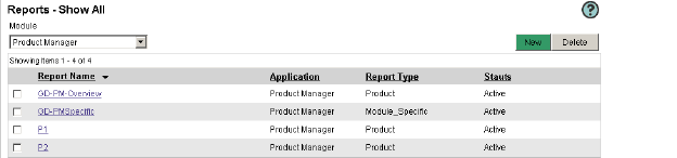
The Reports page
2 Click a Report Name. The Report Details page opens.
1 From the Reports page, select a Module from the list. The page refreshes to list only the reports for the selected application.
2 You may click a column header (Application, Report Type) to sort the list ascending or descending order.
Configuring a Report for the Report Launcher
Figure116 The Report Details page
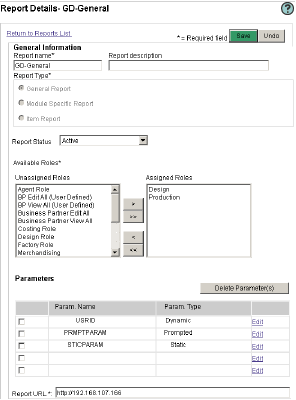
1 From the Reports list, click Actions>New. The Report Details page opens (Figure 106).
2 From the General Information section, enter the Report Name in the field. This field is required.
3 Type a Report Description if needed.
4 Select a Report Type radio button. This field is required.
• General - report will be available from all Fashion PLM modules.
• Module Specific - report will be available from the selected Fashion PLM module.
• Item - report will be available from the selected item.
5 Select a Report Status from the list.
6 Select a Report Category from the list.
7 Select which roles will have access to this report by click a role in the Unassigned Roles list and using the > to move it to the Assigned Roles list.
8 Type the Report URL in the field. This field is required.
9 Click Save.
10 Edit the Report Parameters. See “Adding Report Parameters” on page 133.
Figure117 The Edit Parameter window
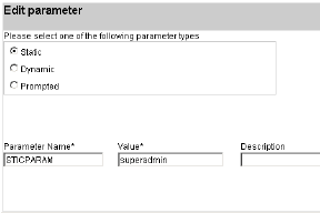
- Static Parameter
1 From the Parameters section of the Report Details page, click the Edit link. The Edit Parameter window opens (Figure 107).
2 Select a parameter type:
• Static
a Enter a Parameter Name in the field. This should match the parameter name in the report. This field is required.
b Enter a Parameter Value in the field. This field is required.
c Enter a Description in the field.
• Dynamic
Figure118 The Dynamic Parameter Type
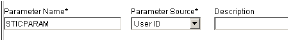
a Enter a Parameter Name in the field. This should match the parameter name in the report. This field is required.
b Enter a Parameter Source in the field. This field is required.
c Enter a Description in the field.
• Prompted
a Select a Parameter Data Type from the list. This field is required.
Figure119 The Prompted Parameter Type
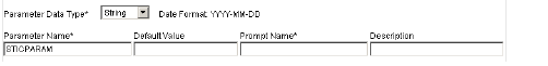
b Enter a Parameter Name in the field. This should match the parameter name in the report. This field is required.
c Enter a Parameter Value in the field. This field is required.
d Enter a Description in the field.
3 Click Save and Close Window. The page is refreshed and the parameters is listed in the Parameters list.
1 From the Parameters section of the Report Details page, select the check boxes of the report parameters you wish to delete.
2 Click Delete Parameter(s). The confirmation message appears.
3 Click OK. The parameter is deleted.
1 From the Reports list, select the check box(es) of the set(s) you wish to copy.
2 Click Action>Copy. The confirmation message appears.
3 Click OK. The set is copied and listed as “Copy of...”.
1 From the Reports list, select the check box(es) of the set(s) you wish to delete.
2 Click Action>Delete. A confirmation message appears.
3 Click OK. The set is removed from the page and from all Reports.
Using Manage Fields, create User Fields, configure your drop-down lists, sort list items, rename items, create dependencies between fields, and add filtering between lists and items.
Manage POMs allows you to add and delete Point of Measures to the POM list.
Manage Operations allows you add operations to calculate labor-related costs for product costing.
Use Size Ratio to create size ratios that can be used in the Color Matrix window when creating Cost Requests in Product Manager.
Vendor Management Templates and Fields are used to set up vendors in Source.
You may configure your drop-down lists and fields in Product Manager, Line Optimizer, and Fabric & Trim. The configuration section of the Administration module allows you to sort lists, add items to existing lists, and create dependencies between the fields.
Using the User Fields feature you can now add your own fields to the Product Manager, Line Optimizer, Source, Storyboard and Fabric & Trim forms. You have the option of adding free text fields of multiple types: alphanumeric, numeric, currency, date, time. You can also define drop-downs and list boxes to be of types static or global. you may also create image fields.
Select on which forms your user fields should appear and use the Form Designer to drag and drop them onto the Form in the section of your choosing.
Figure120 The Manage Fields list
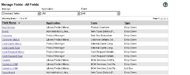
When a new user-defined field is created it must be associated to at least one form variation. It is most efficient to create the form variation that will use the new field before creating the field.
When creating dependencies between fields, you may also apply filtering to your items so that only specified items appear in the field list.
Filtering allows you to minimize the information your users need to view.
1 From the Business Process Management tab, click Manage Fields in the Data Dictionary section. The Manage Fields page appears (Figure 110).
2 Select a letter of the alphabet to navigate to all fields starting with a specific letter.
3 You may select the desired module from the Application list. The Form list is filtered.
4 You may also select the Form from the list. All fields for the selected Application and Form appear.
5 You may sort the list by clicking on a column header.
6 Click the page number to navigate to the next page.
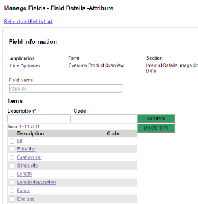
The Field Information window
1 From the Manage Fields window, select Standard Fields from the Manage list. All Standard Fields are listed.
2 Click a Field Name link. The Field Details window opens (Figure 111).
3 Enter a Description and click Add Item to add a field to the list of items. The item appears in the Items list. See “Adding New Items” on page 140.
4 Select the check box(es) of the item(s) you wish to delete, then click Delete Item. See “Sorting Items Alphanumerically” on page 142.
5 Click Save.
Tip You may define which field data is to be pre-selected in the form by clicking on the Default radio button next to the required field. Remember to click Save after specifying the default field.
6 Select Sort Order. See “Sorting Items Alphanumerically” or See “User-Defined Sorting” on page 142.
Tip You may click the Define Sort Order button to define the sort order.
7 Click Save.
8 To return to the filtered field list click the Return to All Fields link.
Tip
You may also click the Manage Fields link on the left-hand side to view a list of all fields.
1 From the Manage Fields list, select User Fields from the Manage list. The list of User Fields appears.
2 Click Actions>New Field. The Manage Fields - New Field page opens.
Figure122 The Manage Fields - New Field page
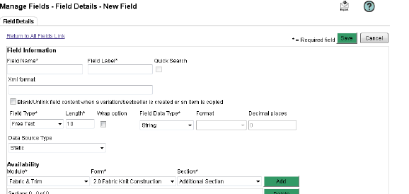
3 Type the Field Name that will appear in the Manage Fields list. This field is required.
4 Type the Field Label name that will appear on the form. This field is required.
Tip
The Field Label can be changed on the Form Designer. See “Setting Label Properties” on page 88.
5 Type an Xml Format tag. This would be used to tag the data from this field in an xml data export should your company implement an export in the future.
6 Click Blank/Unlink field contet when a variation/bestseller is created or an item is copied to change the behavior of the field when item is copied, bestsellered or when a variation is created.
• When items are copied, user-defined fields that have the option selected in the data dictionary will be blanked in the copied item.
• When products are bestsellered, user-defined fields that have the option selected in the data dictionary will be blanked in the bestsellered item.
• When a variation of an item is created, user-defined fields that have the option selected in the data dictionary will behave depending if the field is in the first version, the parent or the new variation. For Parent product, user-defined field with option selected in the data dictionary will have the data copied from the original product and will be unlocked. Modification to the field will not be reflected in variations where form is linked to the parent product. For Variation 1, User-defined field with option selected in the data dictionary will have the data copied from the original product and will be unlocked. For Other variation, User-defined field with option selected in the data dictionary will be blanked and unlocked if form is copied or linked to the parent or to a parent variation.
Note On upgrade, all user-defined fields will have this option unchecked. Existing user-defined fields can be modified and new behavior will be used on new items (new copy, new bestseller, new variations). Copies and carry-over of of type bestseller will not be updated; they will keep the existing data that was copied. Item variation’s copied form will not be updated; they will also keep the existing data that was copied. Item variation’s link form will be updated. User-defined fields on this linked form that have the option selected in the data dictionary will automatically be unlinked from the parent. However, data will remain in the field when variation is opened.
7 Select a Field Type from the list. This field is required.
8 For Free Text:
a Type the field character Length. This field is required.
b Select the Wrap option check box if you wish the text box to automatically wrap.
c Select a Field Data Type from the list. Depending on the selection, the Format and Decimal fields may be locked.
d Select a Format from the list.
e Type the Decimal Places for the field.
• For Drop-Down:
a Type the field character Length. This field is required.
b Select Type -Static, which is a new list of values added to this field, Global/Subset is an existing list of values from another field, or SQL Statement.
c You will need to define the Items for this drop-down list on the Data Source tab. See “Adding Data Source Information” below.
• For Popup List:
a Type the field character Length. This field is required.
b You will need to define the Items for this popup list on the Data Source tab. See “Adding Data Source Information” below.
• For SQL Statement Result:
c You will need to define the SQL statement for this popup list and field mapping on the Data Source tab. See “Adding Data Source Information” below.
• For Image Box there is nothing else to define:
9 Select where this field will be available from the Availability section:
a Select a Module from the list. This field is required.
b Select a Form from the list. This field is required.
c Select a Section from the list. This field is required.
d Click Add. The field is added to the Section List.
e Repeat steps 12-15 if you which this field to be available for multiple Modules, Forms, and Sections.
10 Click Save.
Caution
You can only add a field to the same type of forms (product, fabric, trim etc.) and at the same level. For example, create a field and add to a Product Overview. This can then be added to the header on all product forms but you would not be able to add it to the sketch form body sections because there are multiple sketches. You would not be able to add it to any BOM details forms because they are not product forms, rather they are fabric and trim forms.
11 To return to the filtered field list click the Return to All Fields link.
A maximum of four user fields can be setup to be available for quick search in Product Manager.
1 Log in to Administration.
2 Select the Business Process Management tab.
3 Select Data Dictionary.
4 In the Manage list, select User Fields.
5 Click Action>Set Quick Search.
6 Filter user fields by Form.
a Select Form from the list..
7 In the Non-Quick Search Fields list, select the fields.
8 Click Save.
Adding Data Source Information
1 From the Data Source tab of a User Field, select a field option:
• Standard Field
• Static Drop-Down Field
2 Select a Dictionary field from the list.
3 Modify the Sub-set. See “Modifying a Sub-Set” on page 140.
4 Define the Sort Order. See “Sorting Items Alphanumerically” or “User-Defined Sorting” on page 142.
5 Set the Field Dependencies. See “Setting User Fields Dependencies” on page 139.
6 Click Save.
Adding a Filter to SQL Statement User Defined Fields
There are two types of SQL statement user fields where you can add additional filtering options.
1 Field type: Free text
a Data Source type: SQL statement
2 Field type: Drop down
a Data Source type: Data Dictionary
b Type: SQL statement
Adding One or More Options to the SQL Statement User Field
Once a free text or a drop down user filed of type SQL statement has been created, the Data Source tab will become visible.
1 Create and save/edit a free text or drop down SQL statement user field.
2 Click the Data Source tab. The Field Information page displays.
3 Enter a valid information in the Code field and Key field.
4 Select the option that will be used for filtering (this will be shown in the URL when you are viewing an item in Fashion PLM).
a Product ID (internal Product ID)
b Fabric ID (internal Fabric ID)
c Trim ID (internal Trim ID)
d Node ID (folder ID)
e Item ID
5 The SQL query will be updated automatically to show the additional filter WHERE name_ID=@name_ID (where name is the filter type selected in step 4).
6 Edit the SQL query by entering a valid table name and additional query information.
7 Enter a valid ID in the selected test value ID checkbox and then click Test Query. A dialog opens.
a If SQL statement is valid, the result will display.
b If SQL statement is invalid, an error message will display.
8 Close the dialog and then save your work.
Note if one or more of the filters is not available as part of the URL in the application and form where the user field has been added, the field’s background color will be highlighted in gray. Hovering on the field will display an error message.
Setting User Fields Dependencies
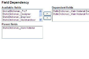
The Fields Dependency section
1 From the Fields Dependency section of the Data Source tab (Figure 113), select a field in the Available Fields list.
Note
Only the user fields that are associated to the same form will be displayed
2 Click the > button to move it to the Dependent Fields list.
Tip
Click < to remove a field from the Dependent Fields list or click << to remove all dependent fields.
3 Click Save.
Note
The Parent Fields list displays all fields upon which the selected field is dependent. This list is read-only.
Figure124 The Select a Sub-set window
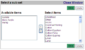
1 From the Data Source tab of a User Field, click the Manage Sub-Set link. The Select a Sub-set window opens (Figure 114).
2 Select a field in the Available Items list.
3 Click the > button to move it to the Dependent Items list.
4 Click Save.
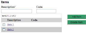
1 From the Items section of the Data Source tab (Figure 115), type a Description in the field. This field is required.
Note
You can only add new items to user fields of type Drop-down or Popup List.
2 Type a Code in the field.
Tip
You may also click New from the Item Detail page.
3 Click Add Item. The item is added to the Items list.
4 Click Save.
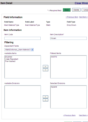
The Item Detail page
1 From the Field Details window, click an item link in the Items list to open the Item Detail page (Figure 116).
2 Add or modify the Item Information.
a Enter an Item Code in the field.
b Enter an Item Description in the field. This field is required.
3 Apply Filtering. See “Applying Item Filtering” below for details.
4 Click Save.
1 From Filtering section of the Item Details page, select a Dependent Field from the list.
2 Click a field in the Available Items list that you wish to filter for the selected field.
3 Click the > button to move it to the Filtered Items list.
Tip
Click < to remove a field from the Dependent Field list or click << to remove all dependent fields.
4 Select a Division from the Available Divisions list, then click > to move it to the Selected Divisions list.
Caution
See “Filtering Rules” on page 19 for important information on filters before removing Division filters.
5 Click Save and Close Window.
Tip
You may also click the Next Item link to modify the Item Details for the next item in the list.
Sorting Items Alphanumerically
Figure127 The Sort Order section
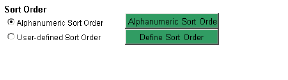
1 From the Sort Order section Data Source page (Figure 117), select the Alphanumeric Sort Order radio button.
2 Click Save. The list is reordered alphanumerically.
Figure128 The Set Sort Order window

1 From the Data Source page, click the User Defined Sort Order radio button.
2 Click the Define Sort Order button. The Set Sort Order window opens (Figure 118).
3 Select an item and use the arrows to move it up or down.
4 Click Apply and close the window.
5 Click Save. The list is sorted as selected.
1 From the Item Detail page, select the item(s) you wish to delete.
2 Click Delete Item. A confirmation message appears.
3 Click OK. The item is deleted.
Warning
This action may not be undone and the item will be permanently deleted.
1 From the Manage Fields window, select User Fields from the Manage list. All User Fields are listed.
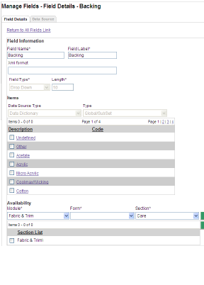
The Field Details window
2 Click a Field Name link. The Field Details window opens (Figure 119).
3 Modify the Field Name. This field is required.
4 Modify the Field Label. This field is required.
5 Modify the XML Format in the field.
6 Modify the Item Details. See “Adding New Items” on page 140.
7 Define where this field will be available from the Availability section:
a Select a Module from the list.
b Select a Form from the list.
c Select a Section from the list.
d Click Add. The selection is listed in the Section List.
8 Click Save.
9 Modify the Data Source information for field types that have this tab. See “Adding Data Source Information” on page 139.
10 To return to the filtered field list click the Return to All Fields link.
1 From the User Field list, select the fields you wish to delete.
2 Click Actions>Delete. A confirmation appears.
3 Click OK. The field is deleted.
Warning
This action may not be undone. The field will be removed from all forms.
The Manage POMs section of the Data Dictionary allows you to build up a library of points of measure and How to Measure images, which are then associated to product classes. This saves time and ensures consistency in your samples, as your business partners get familiar with the same points of measure.
When creating a Smart Grade, you will associate your POMs to a selected Size Category and Range. See “Smart Grade” on page 58.
Figure130 The Manage Points of Measure window
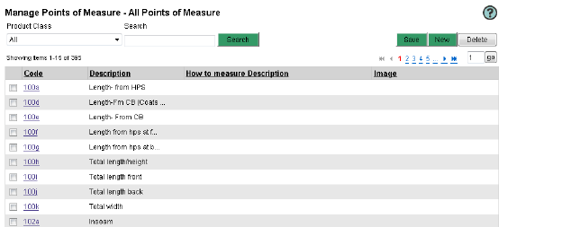
1 From the Business Process Management tab, click Manage POMs in the Data Dictionary section. The All Points of Measure list appears (Figure 120).
2 Select a Product Class from the list. The associated POMs are filtered.
3 Click the Code link to open the Point of Measure Details page.
4 Click the Return to All Points of Measure link to view other POMs.
Tip
You may go to different pages by clicking the page numbers. You may also use the Search button to look for the criteria in the point of measure code and description column.
Figure131 The Point of Measure Details page
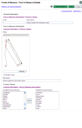
1 From the All Points of Measure list, click Action>New. The Point of Measure Details page opens (Figure 121).
2 Type a POM Code in the field. This field is required.
3 Type a POM Description in the field. This field is required.
4 Click Browse in the How to Measure Information section to navigate to the desired image, then click Open. The image appears.
Note
You may also add Designer sketches or template images from the Library. See “Adding an Image Template” on page 63.
5 Type a How to Measure Description in the field.
6 In the Product Class section, select a Available Product Class from the list, then click > to move it to the Selected Product Class list.
7 Click Save.
Tip
Click Save and New to save this POM and add a new one.
1 From the All Points of Measure list, click Action>Sort POM and select a sort option:
• Alphanumeric-code: the POM list is sorted alphanumerically by the Code field.
• Alphanumeric-description: the POM list is sorted alphanumerically by the Description field.
• User defined: you set the POM order.
2 Click Save. The POMs are sorted as selected.
Figure132 The Set Sort Order window

1 From the All Points of Measure list, click Action>Sort POM>User Defined. The Set Sort Order window opens.
2 Select a POM from the list and use the arrows to move it up or down.
3 Click Apply, then Close Window.
4 Click Save. The POMs are sorted as selected.
1 From the All Points of Measure list, click the check-boxes for the POM to delete.
2 Click Action>Delete. The selected POM are deleted.
Caution
If a POM is associated to a Grade Rule, it is deleted from the grade rule and it becomes a free-text POM in all products using it.
Warning
This action may not be undone and the POM will be permanently deleted.
You will need to create operations before you can create Operation Lists. Operations allow you to calculate labor-related costs for product costing.
Figure133 The Manage Operations window
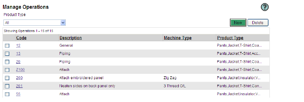
1 From the Business Process Management tab, click Operations in the Data Dictionary section. The Manage Operations page appears.
2 Select a Product Class from the list. The associated operations appear.
3 Click the Code link to open Operation Information page.
4 Click the Return to All Operations link to view other operations.
Figure134 The Set Sort Order window
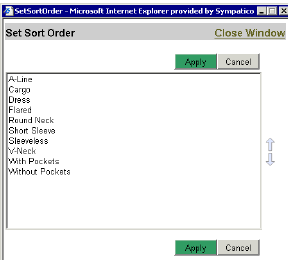
1 From the All Operations list, click Action>Sort Operations>User Defined. The Set Sort Order window opens.
2 Select an Operation from the list and use the arrows to move it up or down.
3 Click Apply, then Close Window.
4 Click Save. The Operations are sorted as selected.
1 From the Manage Operations page, click Action>New. The Operation Information page opens (Figure 128).
Tip
You may also click the New button.
Figure135 The Operation Information page
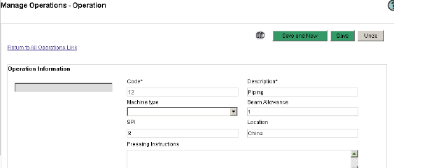
2 Enter a Code in the field. This field is required.
3 Enter the operation name in the Description field. This field is required.
4 Select a Machine Type from the list. Machine Types are entered in the Manage Fields section of the Administration module. See “Manage Fields” on page 135.
5 Type the Seam Allowance in the field.
6 Type the allowable number of stitches per inch in the SPI field.
7 Enter where this operation will be performed in the Location field. Since the country or region will affect your labour costs, you may need to create different operations for each location.
8 Enter Pressing Instruction in the field.
9 Enter Stitching Instructions in the field.
Note
Most operations will either have Pressing Instructions or Stitching Instructions, since these are two types of operations with different Labour costs and rate.
10 Type the amount of time estimated to complete this operation in the Standard Allowable Minutes (SAM) field.
11 Enter the Labor Rate in the field. The rate should be calculated using both the hourly rate of the operator, as well as machine cost and maintenance.
12 You can leave the Labor Rate field empty to calculate an average rate per location or region. See “Creating a List of Operations” on page 67.
13 The Labour Cost is automatically calculated using the SAM and the Labor Rate.
Figure136 The Product Type section

14 Select a Product Type for which this operation applies from the Available Product Type list.
15 Click > to move it to the Selected Product Type list.
16 Click Save and New or Save to return to the Operations list.
1 From the All Operations list, click the check-boxes for the Operations to delete.
2 Click Action>Delete. The selected Operations are deleted.
Caution
If a Operation is associated to an Operations List, it is deleted from the Operations List and it becomes a free-text Operation in all products using it.
Warning
This action may not be undone and the Operation will be permanently deleted.
Users can save time by selecting a size ratio when requesting costing request from a business partner.
Figure137 The Manage Size Ratio list
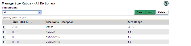
1 From the Business Process Management tab, click Size Ratios in the Data Dictionary section. The Manage Size Ratios page appears.
2 Select a Product Class from the list. The associated size ratios are filtered.
3 Click the Size Ratio ID link to open the Size Ratio Information page.
4 Click the Return to All Size Ratio link to view other size ratios.
1 From the Manage Size Ratios list, click Action>Sort Size Ratio>User Defined. The Set Sort Order window opens.
2 Select a Size ratio from the list and use the arrows to move it up or down.
3 Click Apply, then Close Window.
4 Click Save. The Size ratios are sorted as selected.
1 From the Manage Size Ratios page, click Action>New. The New Size Ratio page opens (Figure 128).
Figure138 The New Size Ratio page
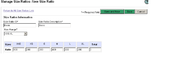
2 Enter a Size Ratio ID in the field. This field is required.
3 Enter a Size Ratio Description in the field. This field is required.
4 Select a Size Range from the list. This field is required. The page is refreshed and all sizes for the selected Size Range appear.
Note
The Size Ratio fields will appear for each of the selected Size Range’s sizes.
5 Enter a ratio for all listed sizes or leave unused sizes empty.
6 Click Save or Save and New to save and add a new Size Ratio. The Total is calculated.
1 From the Manage Size Ratios list, click the check-boxes for the Size Ratios to delete.
2 Click Action>Delete. The selected Size Ratios are deleted.
Create templates for your different types of suppliers in Source. Define which standard and user fields are available for your vendors when viewing the Compliance forms.
Viewing Vendor Management Templates
1 From the Business Process Management tab, click VM Templates in the Data Dictionary section. The Vendor Management Template List page opens.
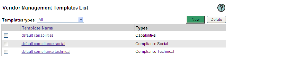
The Vendor Management Template List page
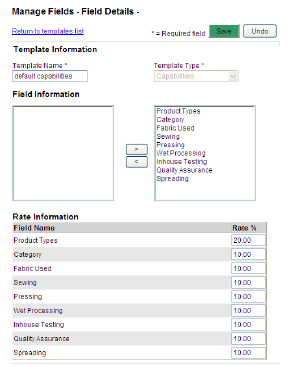
The Template Information page
2 Select a Template Type from the list. The list is filtered by type.
3 Click a Template Name link to open the Template Information page.
4 Modify the template information and click Save.
1 From the Vendor Management Template List page, click New. The Template Information page opens (Figure 140).
2 Enter a Template Name in the field. This field is required.
3 Select a Template Type from the list. The list of available fields appear in the Field Information section.
4 Select available fields and click >. The fields appear in the Rate Information section.
5 Type a Rate % for each select field.
6 Click Save.
1 From the Vendor Management Templates List, click the check-boxes for the VM Templates to delete.
2 Click Delete tab. Confirmation message window appears.
3 Click OK. The selected VM Templates are deleted.
The Vendor Management Field list allows you to add fields per Template Type for use with the Compliance forms of Source.
Viewing Vendor Management Fields
1 From the Business Process Management tab, click VM Fields in the Data Dictionary section. The Vendor Management Field List page opens.
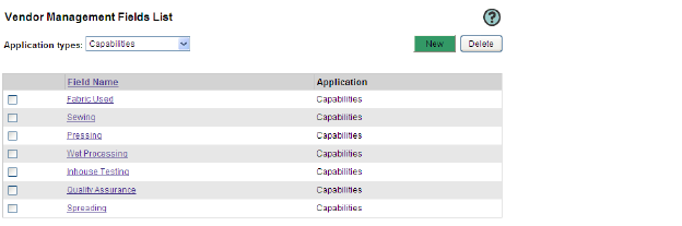
The Vendor Management Template List page
2 Select an Application Type from the list. The list is filtered by type.
3 You may sort the list by clicking on a column header.
4 Click a Field Name link to open the Field Information page.
5 Click the page number to navigate to the next page.
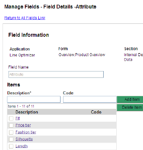
The Manage Fields- Field Details window
1 From the Vendor Management Fields List, click a Field Name link. The Manage Fields- Field Details window opens (Figure 142).
2 Enter an Item Name and click Add Item to add a field to the list of items. The item appears in the Items list.
3 Select the check box(es) of the item(s) you wish to delete, then click Delete Item. The selected items are deleted.
4 Click Save.
5 To return to the field list click the Return to All Fields link.
Tip
You may also click the VM Fields link on the left-hand side to view a list of all fields.
1 From the Vendor Management Fields List, click the check-boxes for the VM Fields to delete.
2 Click Delete tab. Confirmation message window appears.
3 Click OK. The selected VM Fields are deleted.